Method and apparatus for generating a bird's-eye view image

a technology of generating methods and apparatuses, applied in the field of methods and apparatuses for generating birds'-eye view images, can solve the problems of driver confusion/mislead, driver may have a sense of discomfort, and cannot perform stopping operations

Active Publication Date: 2009-05-14
ALPINE ELECTRONICS INC
View PDF17 Cites 61 Cited by
  • Summary
  • Abstract
  • Description
  • Claims
  • Application Information

AI Technical Summary

Benefits of technology

[0024]According to yet another aspect of the present invention, the timing of switching the operation mode from the road-surface projection mode to the virtual-plane projection mode may be delayed to the time at which the vehicle has moved by an amount corresponding to the allowable-movement distance after the obstacle is detected. That is, the operation mode does not have to switch to the virtual-plane projection mode immediately after the obstacle is detected. Since the allowable-movement distance is set bas...

Problems solved by technology

Thus, problems exist in that when the vehicle moves toward the obstacle, the driver may have a sense of discomfort due to, for example, a sudden approach of the obstacle, or alternatively, the driver may not be able to perform a stopping operation in time to avoid colliding with the obstacle/object.
One example of an obstacle that may cause such problems is a clothes-drying pole.
Other examples of obsta...

Method used


Image

  • Method and apparatus for generating a bird's-eye view image
  • Method and apparatus for generating a bird's-eye view image
  • Method and apparatus for generating a bird's-eye view image

Examples


first embodiment

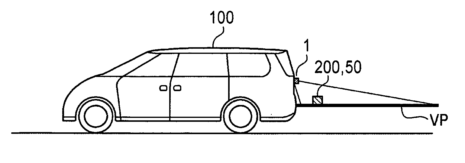
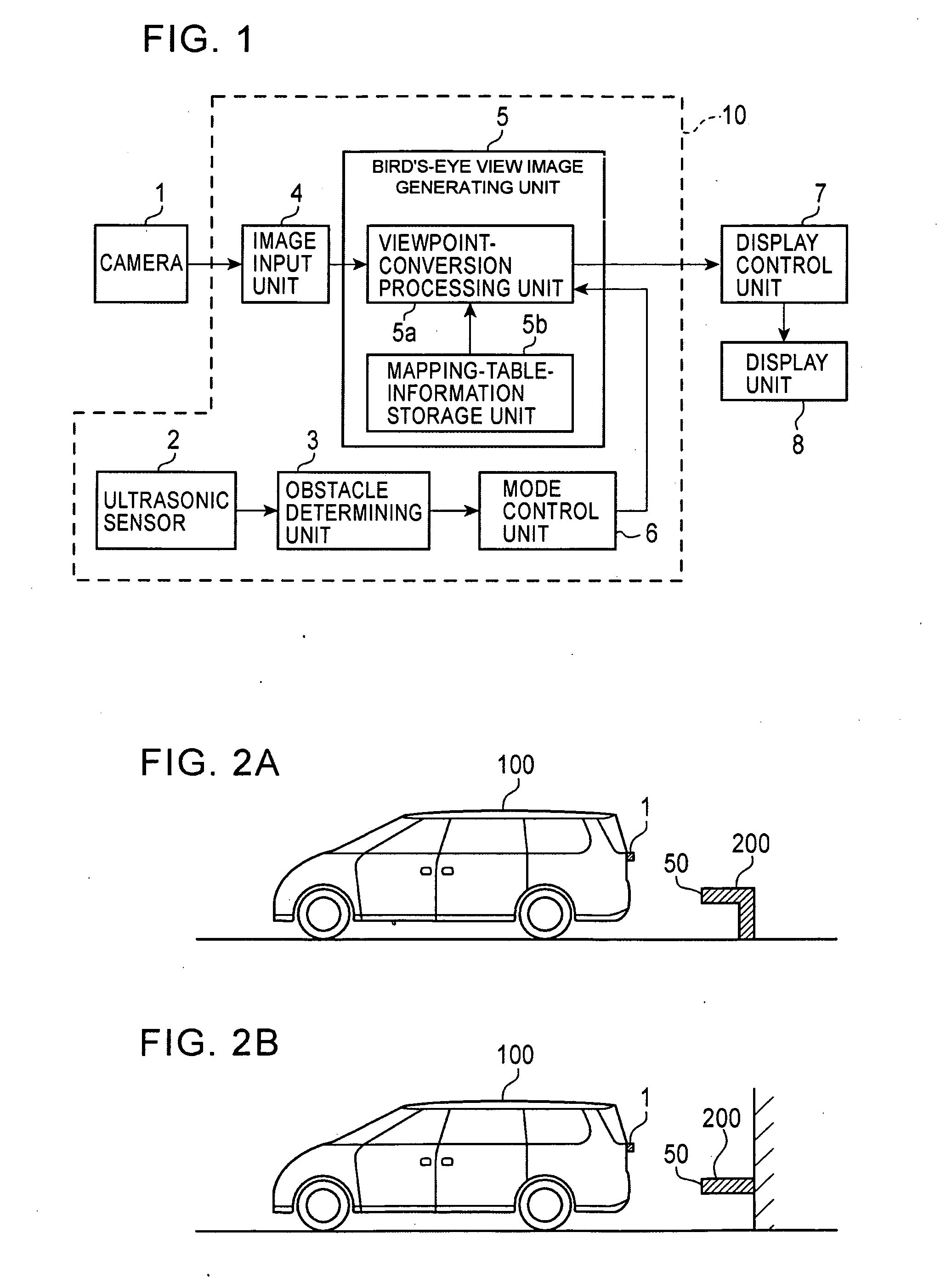
[0038]A first embodiment of the present invention will be described below with reference to the accompanying drawings. FIG. 1 is a block diagram showing an example of the configuration of a bird's-eye view image generating apparatus 10 according to the first embodiment of the present invention. Referring to FIG. 1, a camera 1 is installed on a vehicle to photograph surroundings thereof. The camera 1 is disposed at a predetermined height, for example, on the surface of a rear portion of the vehicle to capture an image behind the vehicle. The camera 1 has, for example, a super-wide-angle lens such as a fisheye lens, and is capable of photographing a wide range behind the vehicle.

[0039]An ultrasonic sensor 2 detects the presence / absence of an obstacle in surroundings of the vehicle and also detects the distance from the vehicle to the obstacle based on a reflected wave of a transmitted ultrasonic wave. The ultrasonic sensor 2 has a sensor head that transmits the ultrasonic wave and rec...

second embodiment

[0062]Next, a second embodiment of the present invention will be described with reference to the accompanying drawings. FIG. 6 is a block diagram showing an example of the configuration of a bird's-eye view image generating apparatus 20 according to a second embodiment of the present invention. In FIG. 6, units denoted by the same reference numerals as those shown in FIG. 1 have the same functions, and thus the descriptions thereof will not be given below.

[0063]The second embodiment shown in FIG. 6 differs from the first embodiment shown in FIG. 1 in at least that a viewpoint-conversion processing unit 5c in the bird's-eye view image generating unit 5 performs a different type of processing than that performed by the viewpoint-conversion processing unit 5a of the first embodiment. That is, instead of the viewpoint-conversion processing unit 5a shown in FIG. 1, in the configuration in the second embodiment shown in FIG. 6 the viewpoint-conversion processing unit 5c performs a differe...

third embodiment

[0068]Next, a third embodiment of the present invention will be described with reference to the accompanying drawings. FIG. 8 is a block diagram showing an example of the configuration of a bird's-eye view image generating apparatus 30 according to a third embodiment of the present invention. In FIG. 8, units denoted by the same reference numerals as those shown in FIG. 1 have the same functions, and thus the descriptions thereof will not be given below.

[0069]The third embodiment shown in FIG. 8 differs from the first embodiment shown in FIG. 1 in at least that a mode control unit 16 performs different processing from that performed by the mode control unit 6 in the first embodiment. That is, the configuration in the third embodiment shown in FIG. 8 includes a mode control unit 16 that performs different processing, as compared to the mode control unit 6 shown in FIG. 1. The third embodiment may have a configuration in which a vehicle movement-amount detecting unit 17 and a table st...


PUM


Abstract

An obstacle detecting unit detects whether an obstacle exists in an area surrounding a vehicle in the direction a camera installed on the vehicle is pointed. If the obstacle is determined to have a portion at a predetermined height above a road surface with which the vehicle may make initial contact when the vehicle moves toward the obstacle, a virtual projection surface is set to the height of the predicted contact portion and viewpoint conversion processing is performed so as to project pixels of an image captured by the camera onto the virtual projection plane. In this way, the height of the projection plane and the height of the predicted contact portion match each other and the distance between the predicted contact portion and the vehicle is accurately expressed on a bird's-eye view image resulting from the viewpoint conversion.

Description

BACKGROUND OF THE INVENTION[0001]1. Related Application[0002]The present application claims priority to Japanese Patent Application Number 2007-292223, filed Nov. 9, 2007, the entirety of which is hereby incorporated by reference.[0003]2. Field of the Invention[0004]The present invention relates to methods and apparatuses for generating bird's-eye view images. More specifically, the present invention relates to a method and an apparatus for generating a bird's-eye view image, as viewed from a virtual viewpoint above a vehicle, by performing viewpoint conversion processing on an image of the surroundings of a vehicle photographed by a camera.[0005]2. Description of the Related Art[0006]Conventional technology exists that captures images of surroundings of a vehicle by using multiple cameras installed at the front, rear, left, and right portions of the vehicle. Viewpoint conversion processing may be performed on the captured images in order to generate a bird's-eye image as viewed fro...

Claims


Application Information

Patent Timeline
IPC IPC(8): H04N7/18G06K9/00
CPCB60Q9/005B60R2300/607G06T7/0044G06T7/74
Inventor IMAMURA, KOSUKE
Owner ALPINE ELECTRONICS INC
Why Eureka
Try Eureka