Mud removing device for steel pipe
A technology of steel pipes and runners, applied in transmission devices, cleaning hollow objects, chemical instruments and methods, etc., can solve the problems of hard cleaning of cement and other attachments, and achieve the effect of easy removal and simple and convenient use
- Summary
- Abstract
- Description
- Claims
- Application Information
AI Technical Summary
Problems solved by technology
Method used
Image

Examples
Embodiment 1
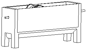
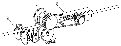
[0025] see Figure 1 to Figure 4 , the present invention provides a steel pipe desilting device, comprising a bracket at the bottom, the upper part of the bracket is a casing, one end of the casing is reserved for a steel pipe inlet, and the other end is provided with a steel pipe outlet, and the casing is provided with a conveying mechanism 1 for conveying steel pipes, and Scraping mechanism 2 for clearing steel pipe attachments;
[0026] The scraping mechanism 2 includes two arc-shaped blades 21 that are arranged oppositely. The arc-shaped blade 21 is a semi-circular body as a whole. The inner diameter of its inner arc-shaped surface is equal to the outer diameter of the steel pipe. Both ends of the 21 axial direction are cutting edges, and the slope of the cutting edge forms an angle of 45 degrees with the plane of the adjacent semi-circular body;
[0027] The two arc-shaped blades 21 are symmetrically arranged on both sides of the steel pipe passing path and reciprocate a...
Embodiment 2
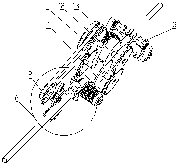
[0037] On the basis of Embodiment 1, the difference from Embodiment 1 is that the transmission mechanism 1 includes a lower runner 11 and an upper runner 12 arranged in half on both sides of the steel pipe passing path, and the circumference of the lower runner 11 is set The groove that can clamp the steel pipe; the upper runner 12 is a semicircular wheel that is equal to the diameter of the lower runner, and its circumferential surface is also provided with a groove that can clamp the steel pipe; the upper and lower runners are respectively connected with a conveying mechanism drive gear 13 are arranged coaxially, and the drive gears 13 of the two conveying mechanisms are meshed with each other;
[0038] The radial surfaces of the lower runner 11 and the upper runner 12 are symmetrically provided with conveying mechanism driving gears 13;
[0039] Conveying mechanism driving gear 13, scraping mechanism driving gear 25 are all vertically arranged, and its same side coaxially a...
Embodiment 3
[0042] see Figure 5 and Figure 6 , on the basis of Embodiment 1 or 2, a knocking mechanism 3 is also provided inside the housing, and the knocking mechanism 3 is arranged between the steel pipe inlet and the conveying mechanism 1, and the knocking mechanism 3 includes The tile-shaped knocking plate 31 is connected to the excitation mechanism, and the knocking plate 31 repeatedly strikes the steel pipe through the excitation mechanism.
[0043] The excitation mechanism includes a bending rod 32 fixedly connected to the knocking plate 31. The bending rod 32 includes a horizontal rod and a vertical rod arranged at the tail end of the horizontal rod. Limiting tube 33, spring 34 is set between the tail end of limiting tube 33 and the front side of the vertical bar, and the sector wheel 35 is set on the front side of the vertical bar, and the sector wheel 35 fits with the front side of the vertical bar;
[0044] One side of the sector wheel 35 is coaxially provided with a knocki...
PUM
 Abstract
Description
Claims
Application Information
 - R&D Engineer
- R&D Manager
- IP Professional
- Industry Leading Data Capabilities
- Powerful AI technology
- Patent DNA Extraction
Browse by: Latest US Patents, China's latest patents, Technical Efficacy Thesaurus, Application Domain, Technology Topic.
© 2024 PatSnap. All rights reserved.Legal|Privacy policy|Modern Slavery Act Transparency Statement|Sitemap