Vacuum cleaner, in particular a hand-held battery cleaner

A technology for vacuum cleaners and base stations, applied in the directions of vacuum cleaners, suction filters, devices for cleaning filters, etc., can solve the problems of impossible regeneration, blockage, hindering regeneration, etc., and achieve the effect of a simple method

Inactive Publication Date: 2017-06-27
VORWERK & CO INTERHOLDING GMBH
View PDF9 Cites 1 Cited by
  • Summary
  • Abstract
  • Description
  • Claims
  • Application Information

AI Technical Summary

Problems solved by technology

[0007] The disadvantage in both cases is that the dust feed in in the emptying direction must avoid a tapering cross-section, wherein a part of the dust can

Method used


Image

  • Vacuum cleaner, in particular a hand-held battery cleaner
  • Vacuum cleaner, in particular a hand-held battery cleaner
  • Vacuum cleaner, in particular a hand-held battery cleaner

Examples


Embodiment Construction

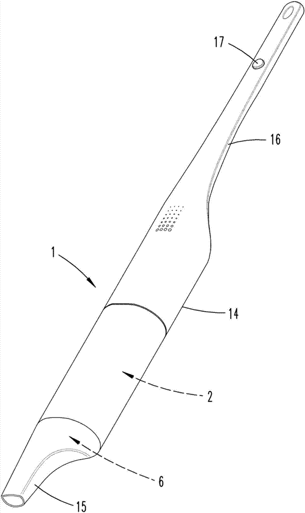
[0025] figure 1 A vacuum cleaner 1 is shown, which is designed here as a battery-operated hand-held vacuum cleaner. The vacuum cleaner 1 has a housing 14 with a filter chamber 2 with an emptying opening 6, a fan 3 (see figure 2 and 3 ) and a handle 16 provided with a switch 17, in this embodiment eg an on key and an off key. In the subregion of the housing 14 with the filter chamber 2 there is a removable suction nozzle 15 which is guided over the surface to be cleaned during the suction operation of the vacuum cleaner 1 . In this case, the dust on the surface to be cleaned is guided through the suction nozzle 15 and the emptying opening 6 into the filter chamber 2 due to the negative pressure generated by the fan 3, in which the dust collects, so that only the The purified air reaches fan 3.

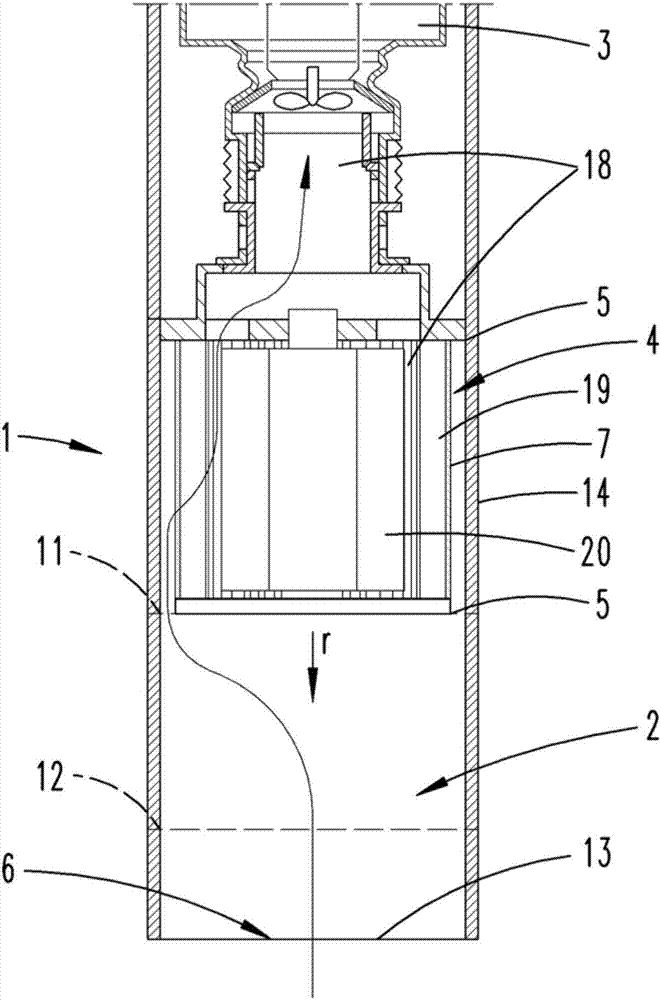
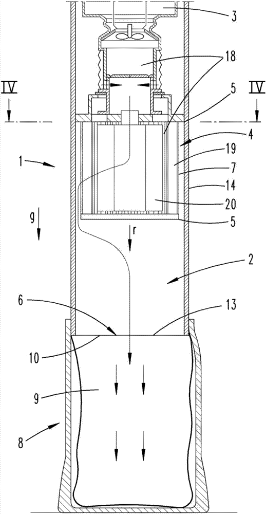
[0026] figure 2 and 3 Shows the longitudinal section of the partial region of the housing 14 with the filter chamber 2 without the base station 8 connected to the filter chamber...


PUM


Abstract

The present invention relates to a vacuum cleaner, in particular a hand-held battery cleaner, having a filter chamber and a fan, wherein the filter chamber is connected to a fan for transporting dust from the surface to be cleaned into the filter chamber during suction operation of the vacuum cleaner and wherein the filter chamber is capable of being connected to the collection chamber for clearing the filter chamber during the regeneration operation. In order to obtain a vacuum cleaner which is ideal for regenerating the filter chamber, it is recommended that the filter chamber be viewed in the clear direction, and in particular between the filter disposed between the filter chamber and the fan and the discharge port connected to the chamber and the chamber, Variable or enlarged cross-section in which the first cross-section along the clear direction is perpendicular to the clear direction without protruding beyond the second cross-section located behind the first cross-section in the clear direction or only from the second cross- Stretch up to 5mm. In addition, the present invention relates to a system composed of a vacuum cleaner and a base station, and a method for operating a vacuum cleaner.

Description

technical field [0001] The invention relates to a vacuum cleaner, in particular a hand-held battery vacuum cleaner, with a filter chamber and a fan, wherein the filter chamber is connected to the fan for transporting dust from the surface to be cleaned to the filter during suction operation of the vacuum cleaner. chamber, and wherein the filter chamber can be connected to a collection chamber for emptying the filter chamber during regeneration operation. [0002] Furthermore, the invention relates to a system comprising such a vacuum cleaner and a base station with a collection chamber for receiving dust contained in a filter chamber of the vacuum cleaner during regenerative operation. [0003] Finally, the invention also relates to a method for operating a vacuum cleaner, wherein during suction operation dust dust is transported from the surface to be cleaned into a filter chamber of the vacuum cleaner by means of a fan of the vacuum cleaner, and wherein during regeneration o...

Claims


Application Information

Patent Timeline
IPC IPC(8): A47L9/10
CPCA47L9/106A47L5/24A47L9/10A47L9/20A47L9/322A47L9/2873
Inventor M.科内利森
Owner VORWERK & CO INTERHOLDING GMBH
Why Eureka
Try Eureka