
Guardrail bending device

A bending device and guardrail technology, applied in the field of guardrail bending devices, can solve the problems of material damage and large stress, and achieve the effect of improving safety and avoiding bending fractures.

Inactive Publication Date: 2018-08-10
安徽雄风防护设施有限公司
View PDF10 Cites 2 Cited by
  • Summary
  • Abstract
  • Description
  • Claims
  • Application Information

AI Technical Summary

Problems solved by technology

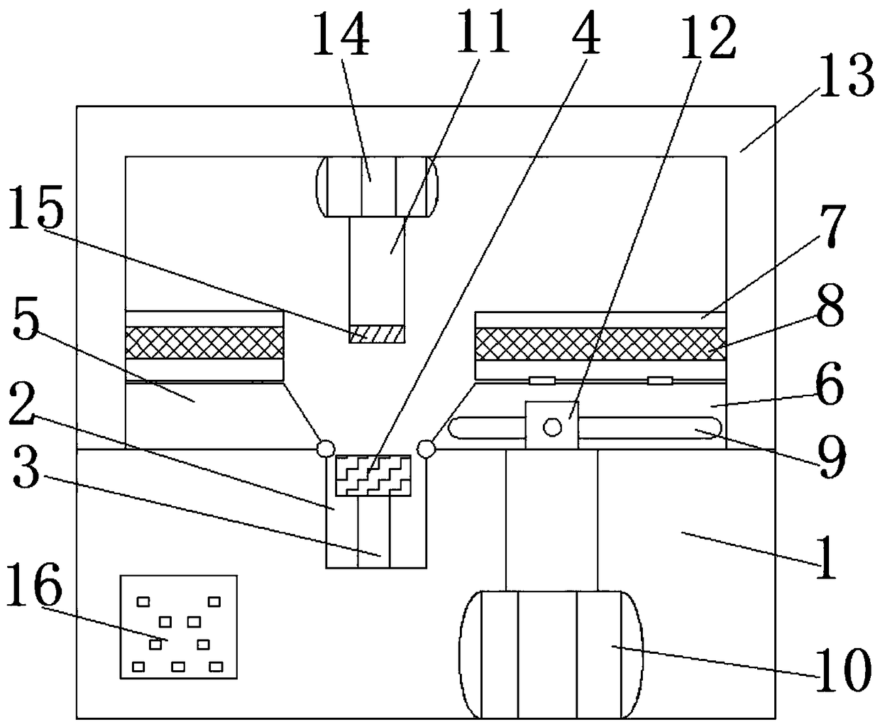
[0004] The purpose of this invention is to solve the problem of material damage caused by excessive local stress in traditional stamping and bending, and propose a guardrail bending device

Method used


Image

  • Guardrail bending device
  • Guardrail bending device
  • Guardrail bending device

Examples


Embodiment Construction

[0019] The following will clearly and completely describe the technical solutions in the embodiments of the present invention with reference to the accompanying drawings in the embodiments of the present invention. Obviously, the described embodiments are only some, not all, embodiments of the present invention.

[0020] In describing the present invention, it should be understood that the terms "upper", "lower", "front", "rear", "left", "right", "top", "bottom", "inner", " The orientation or positional relationship indicated by "outside", etc. is based on the orientation or positional relationship shown in the drawings, and is only for the convenience of describing the present invention and simplifying the description, rather than indicating or implying that the referred device or element must have a specific orientation, so as to Specific orientation configurations and operations, therefore, are not to be construed as limitations on the invention.

[0021] refer to Figure ...


PUM


Abstract

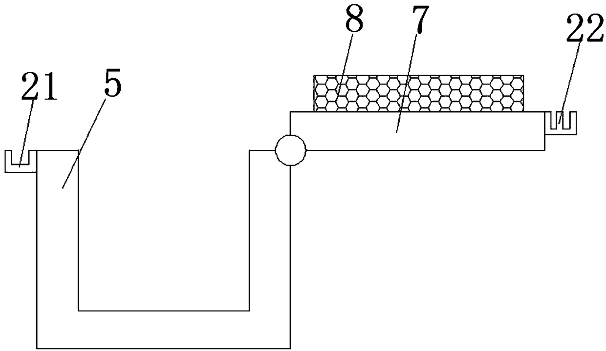
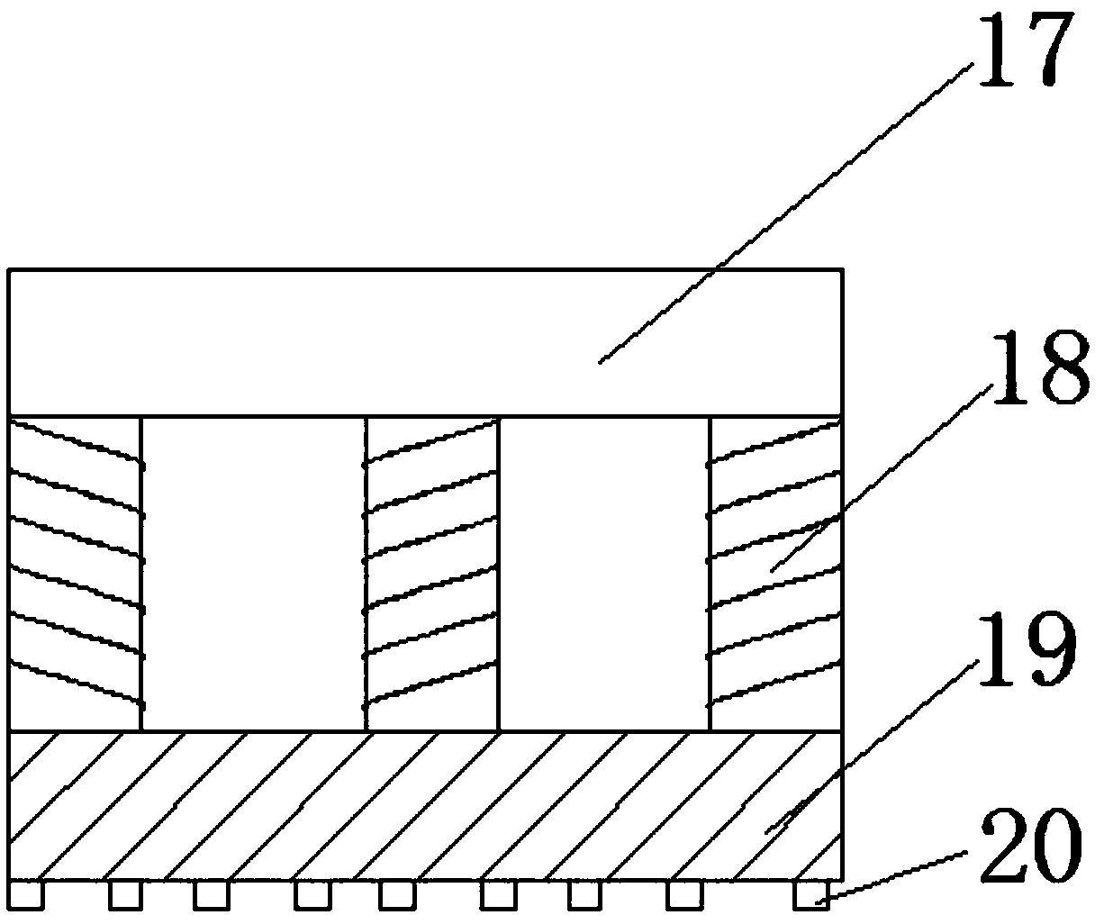
The invention discloses a guardrail bending device which comprises a base. An inner cavity of the base is hollow; a longitudinally arranged groove is formed in the top part of the base; a rectangularopening parallel to the groove is formed in the top part of the base; uniformly distributed electric telescopic rods are longitudinally and fixedly connected to a bottom inner wall of the groove; heating components are fixedly connected to telescopic ends of the electric telescopic rods; longitudinally and uniformly distributed first limiting slots and second limiting slots are movably connected to the left side and the right side of the top end of the groove through hinges; cover plates are movably connected to the top parts of the first limiting slots and the second limiting slots through hinges; rubber pads are arranged on the inner sides of the cover plates; sliding chutes are formed in horizontal outer side walls of the second limiting slots; and longitudinally and uniformly distributed first hydraulic pumps are connected to a bottom inner wall of the base. The guardrail bending device provided by the invention is simple in structure and convenient to operate; a guardrail is pre-heated so as to be bent, and meanwhile, the strength of the guardrail is effectively maintained; and meanwhile, the pressure is buffered, so that the problem of damage caused by excessive pressure is solved.

Description

technical field [0001] The invention relates to the technical field of guardrail bending devices, in particular to a guardrail bending device. Background technique [0002] As consumers have more and more demands on the appearance of guardrails, many guardrail parts need to be bent. Traditional bending equipment generally adopts direct stamping to make guardrail parts bend into the shape set by the mold. However, Due to the high stamping force, and most of the guardrail parts are hollow structures, it is easy to crush the guardrail parts during the stamping process, resulting in an increase in defective products and a great waste of materials. Moreover, the current stamping and bending methods, the bending process If it exceeds the tensile strength of the material, it will cause damage; even if it does not exceed the tensile strength of the material, the fatigue strength will decrease, which will bring safety hazards. [0003] According to the above problems, the present in...

Claims


Application Information

Patent Timeline
Patent Type & Authority Applications(China)
IPC IPC(8): B21D7/06B21D7/16
CPCB21D7/06B21D7/162
Inventor 查何南熊集泉毕达熊根兰
Owner 安徽雄风防护设施有限公司
Learn More