
A metal pipe cutting device

A technology for metal pipes and cutting devices, which is applied in the direction of shearing devices, shearing machine accessories, metal processing equipment, etc., can solve the problems that the cutting speed cannot be guaranteed, and the position of metal pipes cannot be guaranteed, so as to improve cutting efficiency, Realize the effect of two-way cutting

Active Publication Date: 2019-09-13
SUZHOU DOUBLE GOLD IND
View PDF8 Cites 1 Cited by
  • Summary
  • Abstract
  • Description
  • Claims
  • Application Information

AI Technical Summary

Problems solved by technology

The above-mentioned structure is simple and easy to operate, but it cannot guarantee the stable position of the metal pipe during the cutting process, and the cutting speed cannot be guaranteed at the same time

Method used

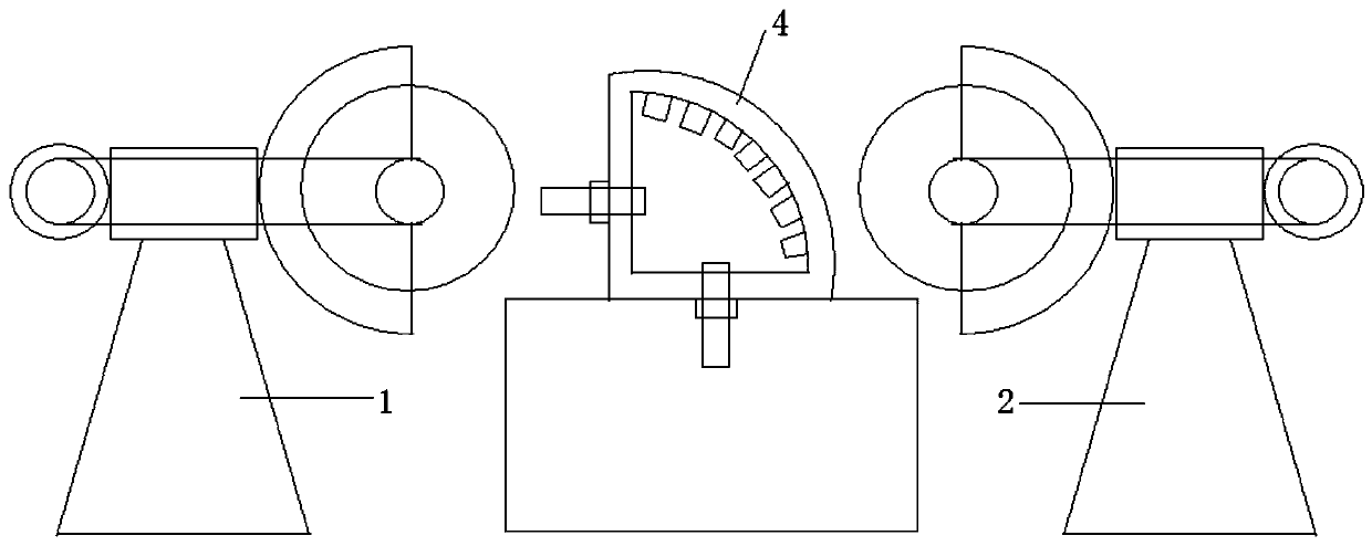

Image

  • A metal pipe cutting device
  • A metal pipe cutting device
  • A metal pipe cutting device

Examples


Embodiment Construction

[0023] The present invention is described in further detail now in conjunction with accompanying drawing. These drawings are all simplified schematic diagrams, which only illustrate the basic structure of the present invention in a schematic manner, so they only show the configurations related to the present invention.

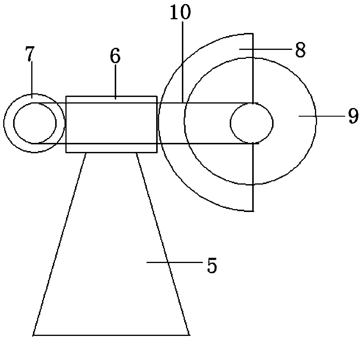
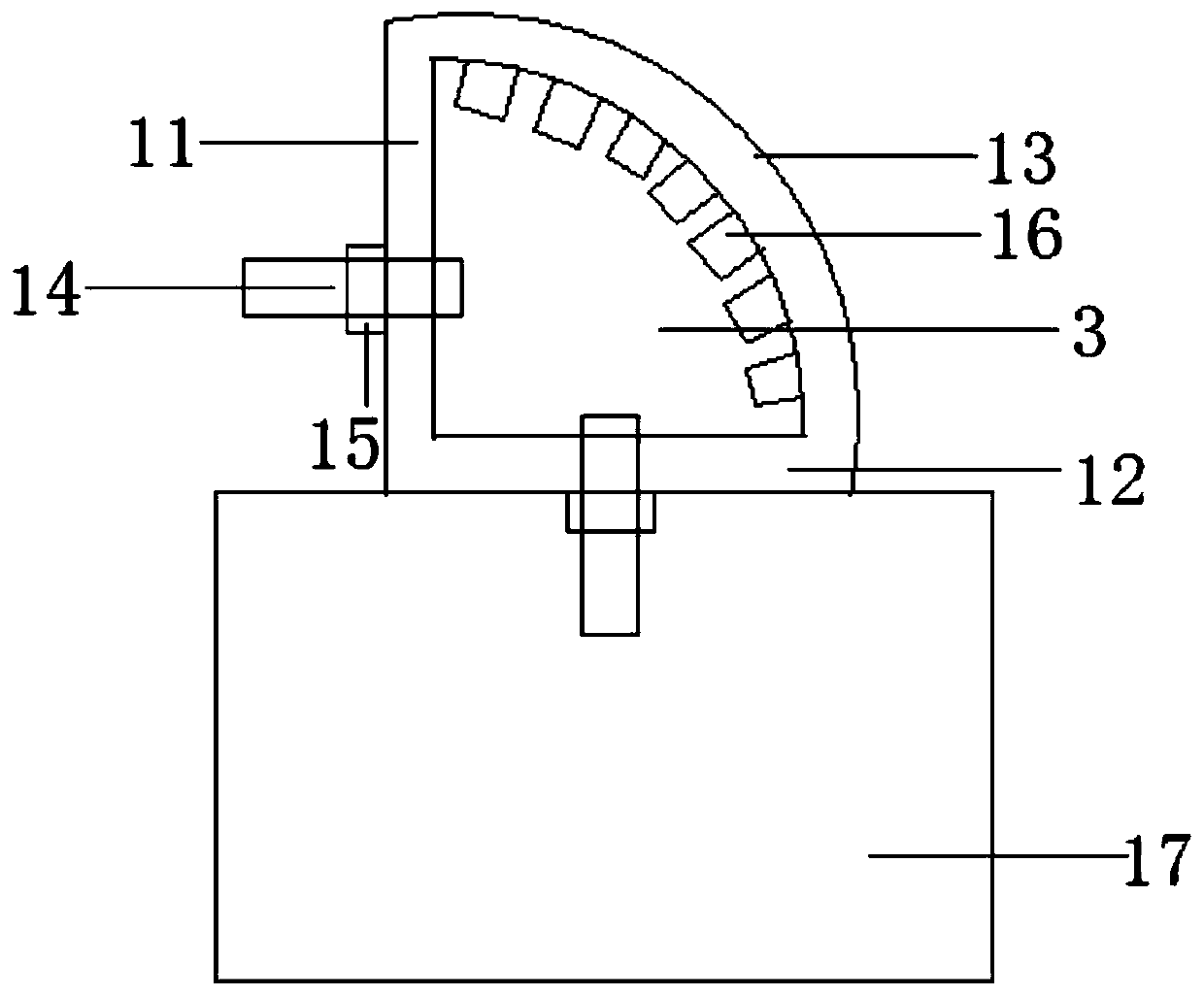
[0024] Such as Figure 1-3 As shown, the present invention includes the following parts: 1 is a first cutting device, 2 is a second cutting device, 3 is a first clamping device, 4 is a second clamping device, 5 is a support frame, 6 is a support block, 7 is the rotating motor, 8 is the cutting cover, 9 is the blade, 10 is the belt, 11 is the first clamping surface, 12 is the second clamping surface, 13 is the curved surface, 14 is the rotating shaft, 15 is the rotating nut, 16 is Elastic sawtooth, 17 is base.

[0025] A metal pipe cutting device of the present invention includes a cutting group and a clamping group, the clamping group is used to clamp the me...


PUM


Abstract

The invention relates to a metal tube cutting device. The metal tube cutting device comprises cutting sets and a clamping set, wherein the clamping set is used for clamping a to-be-cut metal tube; andthe cutting sets are arranged on two sides of the to-be-cut metal tube and simultaneously cut the to-be-cut metal tube. The metal tube cutting device is simple in structure and convenient to operate,guarantees the stability of the metal tube in a cutting process, performs bidirectional simultaneous cutting and is improved in cutting efficiency.

Description

technical field [0001] The invention relates to a metal pipe material cutting device, which belongs to the field of cutting machinery. Background technique [0002] With the development of the modern mechanical processing industry, the requirements for cutting quality and precision are constantly improving, and the requirements for improving production efficiency, reducing production costs, and highly intelligent automatic cutting functions are also increasing. At present, the cutting machines on the market are divided into flame cutting machines, plasma cutting machines, laser cutting machines, water cutting, etc. Among them, the laser cutting machine has the fastest efficiency, the highest cutting precision, and the cutting thickness is generally small; the cutting speed of the plasma cutting machine is also the Soon, the cutting surface has a certain slope; the flame cutting machine is aimed at thicker carbon steel materials; the laser cutting machine has the fastest effi...

Claims


Application Information

Patent Timeline
Patent Type & Authority Patents(China)
IPC IPC(8): B23D33/02B23D19/04
Inventor 时金明崔斌
Owner SUZHOU DOUBLE GOLD IND
Learn More