Injection mold for oil pot lid

An injection mold and pot lid technology, which is applied in the field of injection molds for oil pot lids, can solve the problems of high mold processing cost, complex mold structure, low injection efficiency, etc. Effect

Pending Publication Date: 2018-08-14
思柏精密科技股份有限公司
View PDF0 Cites 3 Cited by
  • Summary
  • Abstract
  • Description
  • Claims
  • Application Information

AI Technical Summary

Problems solved by technology

[0003] like Figure 13 As shown, the structure of the oil pot is relatively special, and the spout 92 on the pot lid 91 is inclined. If the structure adopts ordinary two ha

Method used


Image

  • Injection mold for oil pot lid
  • Injection mold for oil pot lid
  • Injection mold for oil pot lid

Examples


Embodiment Construction

[0046] The present invention will be further described now in conjunction with accompanying drawing.

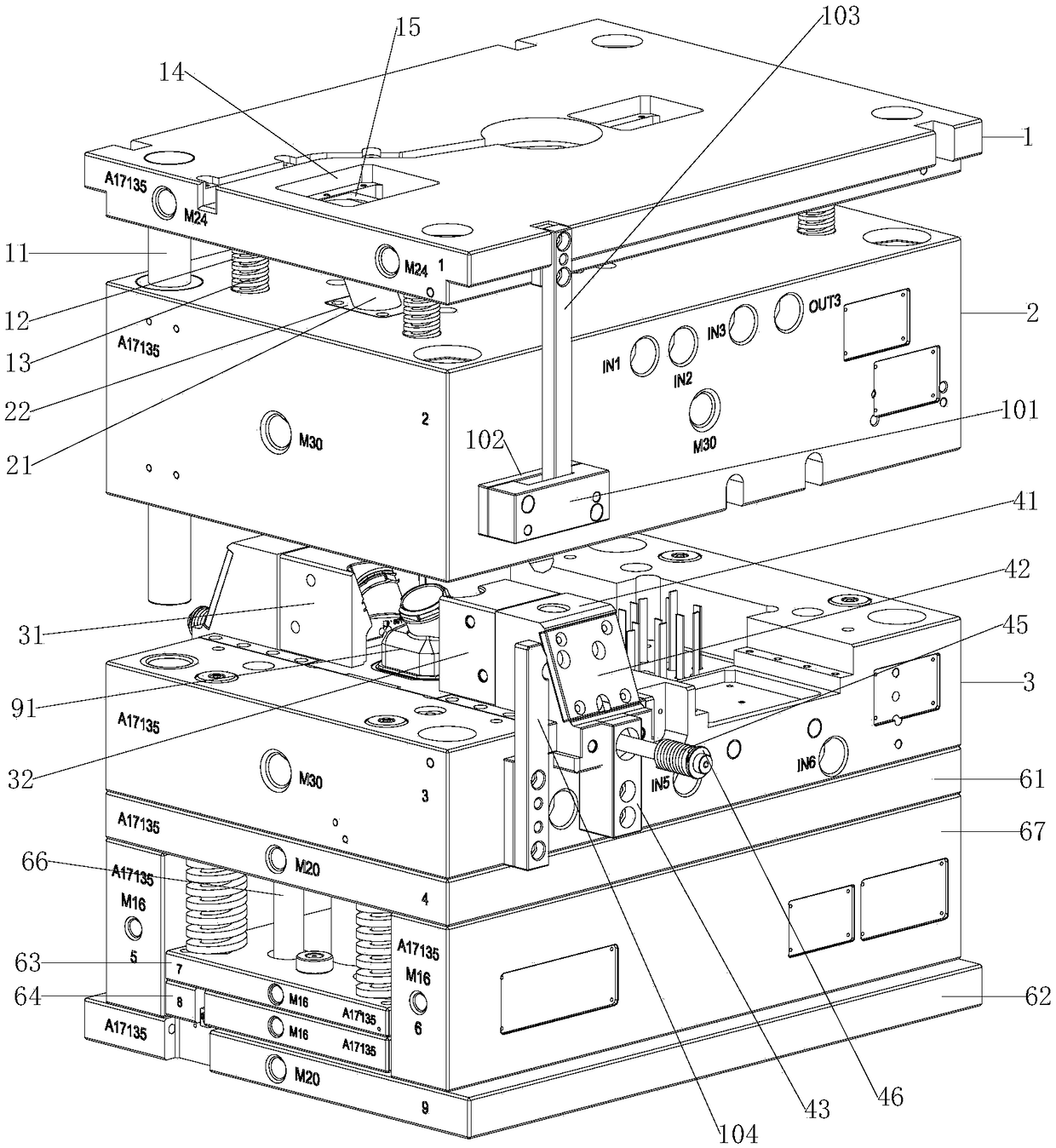
[0047] Such as Figure 1 to Figure 9 Shown, a kind of injection mold of oil pot lid, comprises pot spout core-pulling rod 21, pot lid upper mold core 20, pot lid large side mold core 31, pot lid small side mold core 32 and pot lid lower mold core 33 .

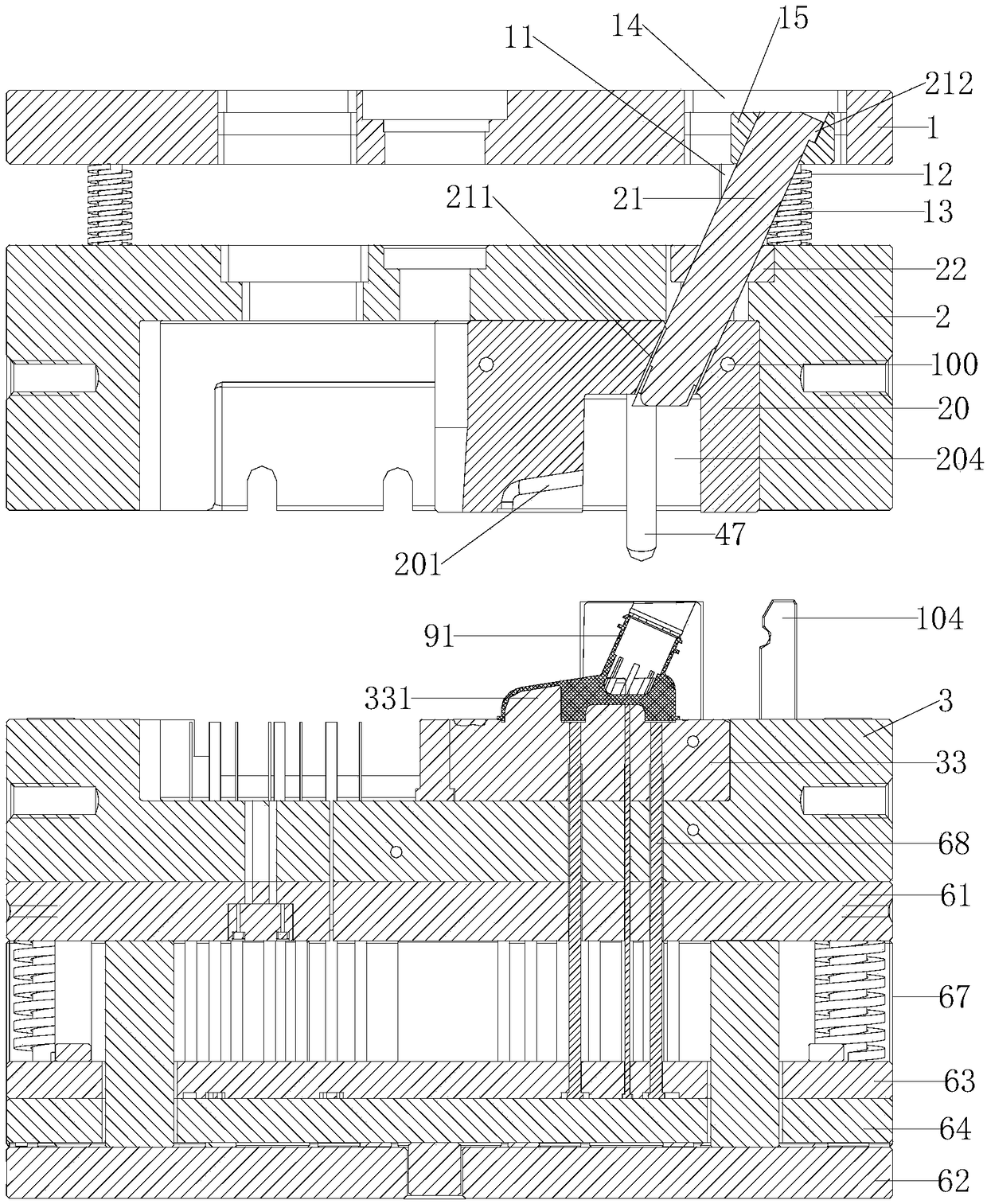
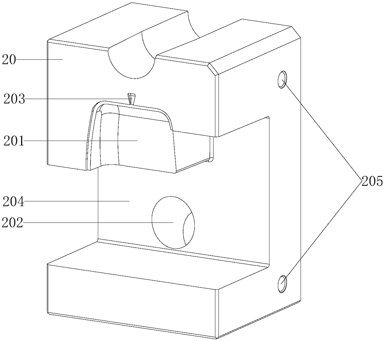
[0048] Such as figure 1 , figure 2 and image 3 As shown, the pot lid upper mold core 20 is fixed on the upper template 2, and the bottom of the pot lid upper mold core 20 is provided with a pot lid cavity A201, a pot lid upper gate 203 and a pot lid side mold core groove 204. The gate 203 communicates with the pot lid cavity A201, the top of the mold core 20 on the pot lid is provided with a spout core-pulling inclined hole 202, and the spout core-pulling inclined hole 202 communicates with the pot lid side mold core groove 204.

[0049] Such as Figure 4 and Figure 5 As shown, the bottom of the large side mold core...


PUM


Abstract

The invention relates to an injection mold for an oil pot lid. A pot lid upper mold core is fixed to an upper mold plate and provided with a pot lid mold cavity A, a pot lid upper sprue, a pot lid side mold core groove and a pot nozzle core pulling inclined hole, a pot lid large-side mold core is provided with a pot lid mold cavity B and a pot nozzle mold cavity A, and a pot lid small-side mold core is provided with a pot lid mold cavity C and a pot nozzle mold cavity B; a pot nozzle mold core is arranged at one end of a pot nozzle core pulling rod, and the other end of the pot nozzle core pulling rod is slidably installed on an upper mold holder and movably inserted into the pot nozzle core pulling inclined hole; the pot lid large-side mold core and the pot lid small-side mold core are movably inserted into the pot lid side mold core groove and connected with a pot lid sliding mold splitting device separately, and the sliding mold splitting device is installed on a lower mold plate; the top of a pot lid lower mold core is provided with a pot lid mold core and a pot lid lower sprue; and the pot lid lower mold core, the pot nozzle core pulling rod, the pot lid upper mold core, the pot lid large-side mold core and the pot lid small-side mold core are combined together to form a pot lid mold cavity. According to the mold, a pot lid can be molded at a time, the structure is reliable, running is stable, and an auxiliary device is not needed.

Description

technical field [0001] The invention relates to a mold, in particular to an injection mold for the lid of an oil pot. Background technique [0002] Generally, the lower end of the power steering oil pot is tightly sleeved on the connecting bracket with the hydraulic pump, and there is an oil return port on the side, which is connected to the low-pressure oil return pipe. Internal hydraulically assisted lubricating oil maintains fluid level between minimum and maximum oil level marks. The oil can be replaced and supplemented by unscrewing the oil can cover on the upper end of the oil can. Therefore, when the lower end surface of the oil pot is guaranteed to be firmly and tightly matched with the connecting bracket and has excellent airtightness, it only needs to be disassembled and reassembled when the hydraulic pump is repaired and replaced. [0003] Such as Figure 13 As shown, the structure of the oil pot is relatively special, and the spout 92 on the pot lid 91 is incli...

Claims


Application Information

Patent Timeline
IPC IPC(8): B29C45/33B29C45/44
CPCB29C45/33B29C45/4435
Inventor 戚永幸陈有桦姜校平栗原洋上田雄史
Owner 思柏精密科技股份有限公司
Why Eureka
Try Eureka