Pipe joint

A technology for pipe joints and joint pipes, which is applied in the field of pipe joints, can solve the problems of easy displacement of elastic snap rings, increased production costs, and poor sealing effects, and achieves the effects of simple structure, reduced assembly parts, and low production costs

Inactive Publication Date: 2018-08-17
广东思豪流体技术有限公司
View PDF5 Cites 1 Cited by
  • Summary
  • Abstract
  • Description
  • Claims
  • Application Information

AI Technical Summary

Problems solved by technology

[0002] Pipe joints are widely used in the existing technical field. The connection methods generally adopt two types of joints: threaded connection and quick connection. Add more sealing parts, and at the same time, fix the pipeline so that it is not easy to loosen. The structure is generally more complicated, and more parts are used, which increases the production cost. At the same time, due to the large number of parts, some parts are easily damaged during use. If one part is extremely bad, the entire joint will be scrapped, and the use cost is high. At the same time, the elastic snap ring of the prior art is very easy to shift during use, so that the sealing effect is poor.

Method used


Image

  • Pipe joint
  • Pipe joint
  • Pipe joint

Examples


Embodiment Construction

[0012] The specific embodiments of the present invention will be further described in detail below with reference to the accompanying drawings.

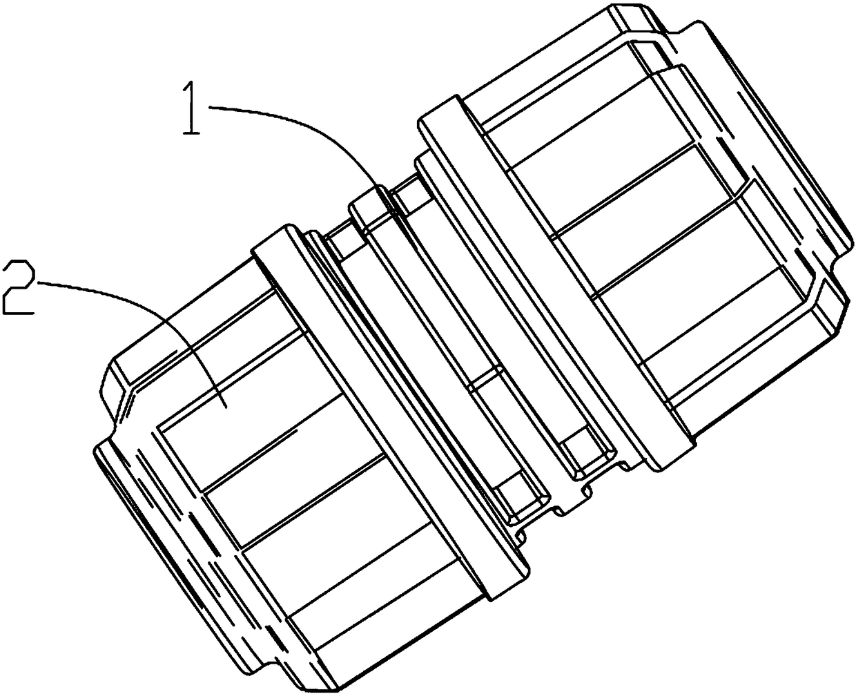
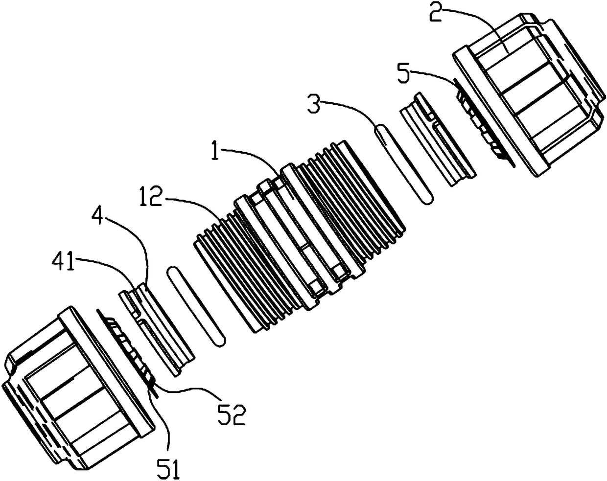
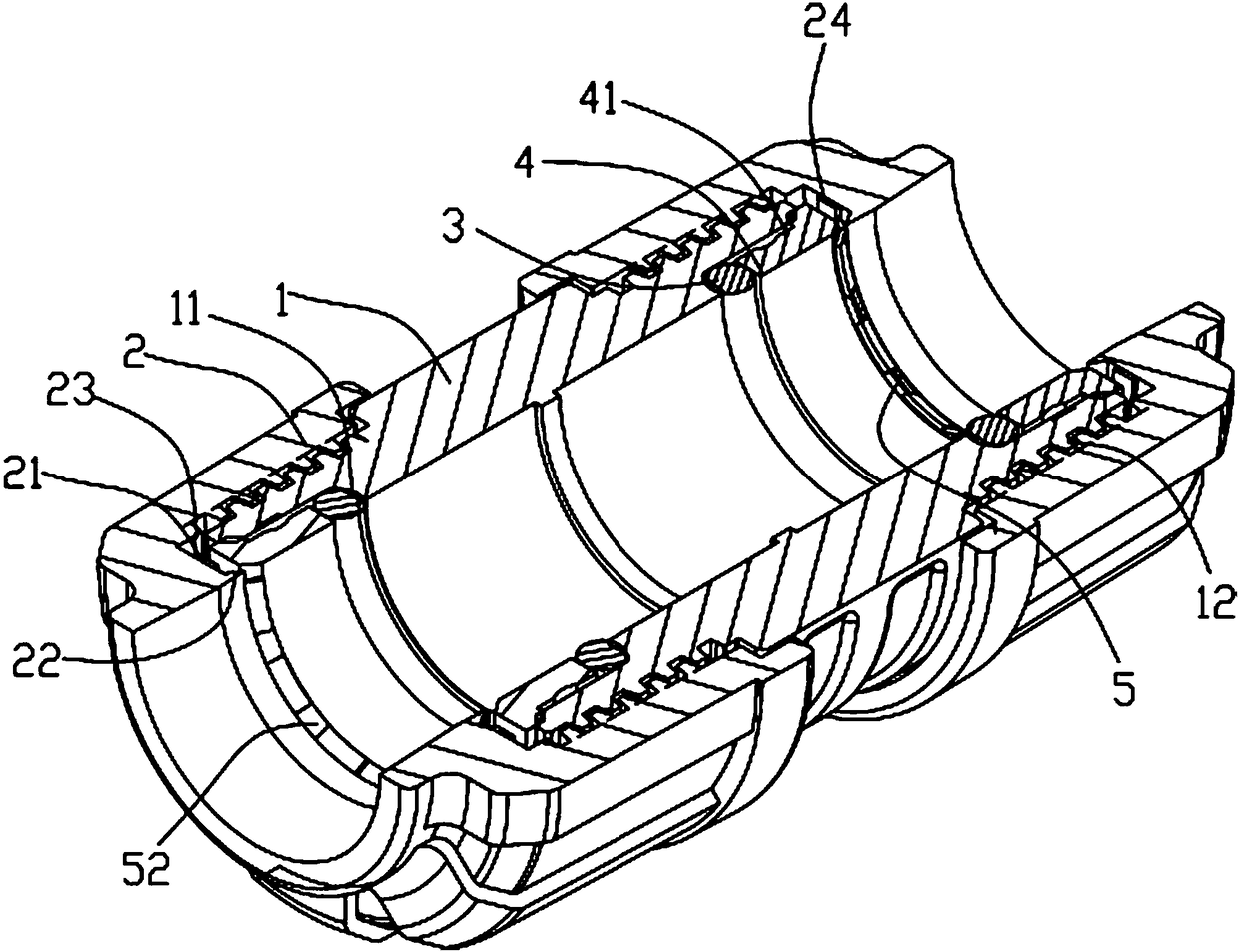
[0013] see attached Figure 1-3 , the present invention includes a joint pipe 1 and a gland 2 sleeved on both ends of the joint pipe 1, the gland 2 and the joint pipe 1 are detachably connected by threads, and the end of the joint pipe 1 is provided with a snap ring seat 4 , one end of the snap ring seat 4 extends into the inside of the joint pipe 1 and is in contact with the sealing ring 3 arranged in the joint pipe 1. The other end of the snap ring seat 4 is provided with an elastic snap ring 5, which is elastic The snap ring 5 includes a ring body 51 and claw teeth 52 . The claw teeth 52 are flanged toward the snap ring seat 4 , and a bevel ring is provided at the opening of the snap ring seat 4 , and the claw teeth 52 abut against the bevel ring. Above, the port of the end head of the joint pipe 1 is a conical port, the other en...


PUM


Abstract

The invention discloses a pipe joint. The pipe joint comprises a joint pipe and glands sleeving the two ends of the joint pipe; the glands are detachably connected with the joint pipe through threads;the heads of the ends of the joint pipe are each provided with a snap ring seat, one end of each of the snap ring seats stretches into the joint pipe and abuts against a sealing ring arranged in thejoint pipe, and the other end of each of the snap ring seats is provided with an elastic snap ring; each elastic snap ring comprises a ring body and claw teeth, the claw teeth are turned up towards the corresponding snap ring seat, an opening of the snap ring seat is provided with an inclined ring, and the claw teeth abut against the inclined ring; ports of the heads of the ends of the joint pipeare conical ports; the other ends of the snap ring seats are provided with circular truncated cone rings matched with the conical ports; a boss is arranged in the position, close to the head of the end of the joint pipe, of the interior of each gland and provided with an annular protrusion protruding towards the corresponding claw teeth; the inner walls of the glands, the bosses and the annular protrusions form grooves, the ring bodies are arranged in the grooves, and in addition, the annular protrusions abut against the inner circles of the ring bodies; and the annular protrusions are conicalplatforms, and the cone angle of the conical platforms is smaller than the cone angle formed by the claw teeth.

Description

technical field [0001] The invention relates to the field of joints, in particular to a pipe joint. Background technique [0002] Pipe joints are widely used in the existing technical fields, and the connection methods are generally two types of threaded joints and quick-connect joints. Add more sealing parts, and at the same time, it is necessary to fix the pipeline so that it is not easy to loosen. The structure is generally more complicated, and many parts are used, which increases the production cost. At the same time, because of the many parts, some parts are easily damaged during use , if one component is badly damaged, the entire joint will be scrapped, and the use cost is high. At the same time, the elastic snap ring of the prior art is very prone to displacement during use, so that the sealing effect is poor. SUMMARY OF THE INVENTION [0003] The invention discloses a pipe joint to solve the deficiencies of the prior art. [0004] In order to solve the above-men...

Claims


Application Information

Patent Timeline
Patent Type & Authority Applications(China)
IPC IPC(8): F16L19/02
CPCF16L19/025
Inventor 周富强
Owner 广东思豪流体技术有限公司
Why Eureka
Try Eureka