Electric energy meter display device

A technology for display devices and electric energy meters, which is applied in the field of electric energy meters, and can solve problems such as waste, inability to replace batteries, and inconvenient installation methods

Pending Publication Date: 2018-08-17
NINGBO SANXING MEDICAL & ELECTRIC CO LTD
View PDF7 Cites 0 Cited by
  • Summary
  • Abstract
  • Description
  • Claims
  • Application Information

AI Technical Summary

Problems solved by technology

[0003] At present, there is a battery in the display device of the electric energy meter. Usually, the battery is welded on the circuit board, and the battery cannot be replaced. cause waste of resources
[0004] In order to solve the above technical problems, the existing electric energy meter display device is equipped

Method used


Image

  • Electric energy meter display device
  • Electric energy meter display device
  • Electric energy meter display device

Examples


Embodiment 1

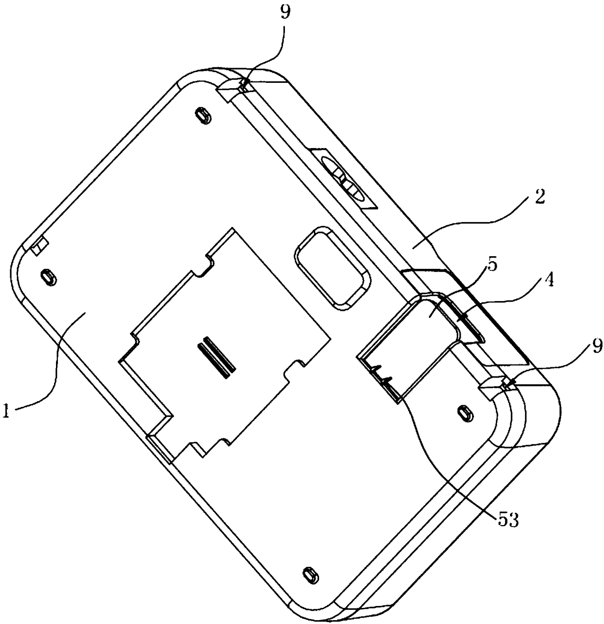
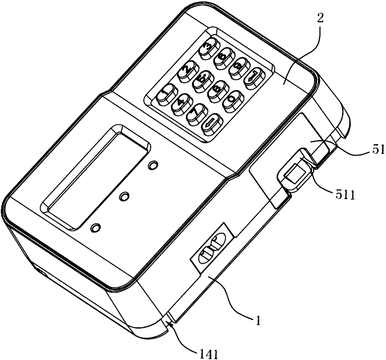
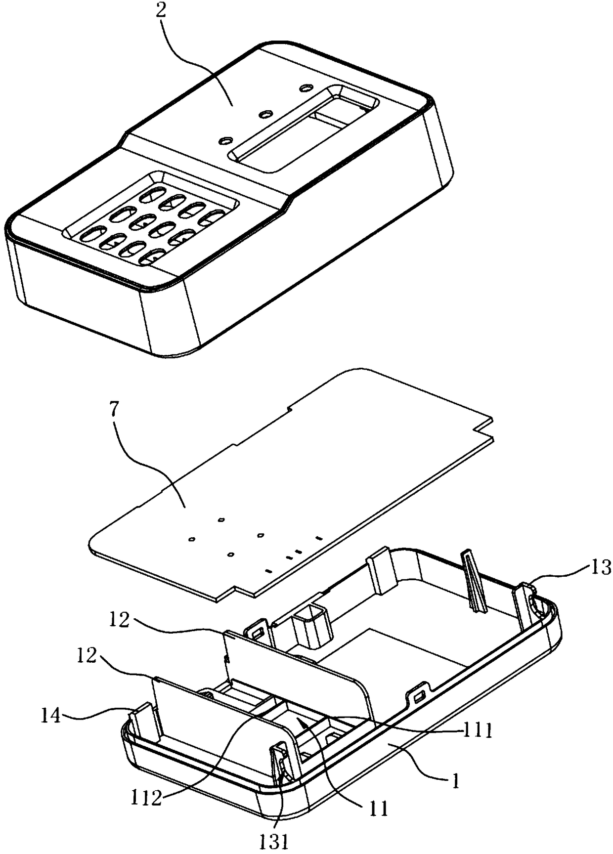
[0048] Such as Figure 1 to Figure 14 Shown is the first preferred embodiment of the electric energy meter display device of the embodiment of the present invention. The watt-hour meter display device includes a battery box 3, a base 1, a cover body 2 arranged on the base 1, and a PCB board 7. The base 1 is formed with a mounting groove 11 for accommodating the battery box 3, and the base 1 and the cover body 2 An installation opening 4 for inserting the battery box 3 into the installation groove 11 is formed on the side wall, and a buckle structure for cooperating with the battery box 4 to limit the position is provided in the installation opening 4 .

[0049] The buckle structure has various structural forms, which can be a buckle hole or a block. In this embodiment, the buckle structure is arranged in the installation groove 11 and includes a belt guiding slope that is snapped and positioned with the battery box 3 When the battery case 3 is inserted into the installation p...

Embodiment 2

[0058] Such as Figure 15 to Figure 16 Shown is the second preferred embodiment of the present invention. The difference between this embodiment and the above-mentioned first embodiment is only that the structure of the metal elastic contact is different, specifically, the metal elastic contact 81 includes a middle part 813 and extension parts 814 extending outward from both ends of the middle part 813, The extension part 814 has the above-mentioned insertion part 810 extending upwards, the middle part 813 is bent to the side away from the extension part 814 to form a bent part 813a, the bent part 813a is inserted into the assembly groove 32, and the The bent portion 813 a has a contact 815 electrically connected to the first battery 311 or the second battery 312 .


PUM


Abstract

The invention provides an electric energy meter display device comprising a battery case. The display device consists of a pedestal and a cover body arranged on the pedestal. A mounting groove for accommodating the battery case is formed in the pedestal; mounting openings for insertion of the battery box into the mounting groove are formed in the side walls of the pedestal and the cover body; andbuckle structures for cooperation with the battery case for limiting are arranged in the mounting openings. According to the electric energy meter display device based on the reasonable design, the mounting groove for accommodating the battery case is formed in the pedestal of the display device and the mounting openings for insertion of the battery box into the mounting groove are formed in the side walls of the pedestal and the cover body, so that the battery case is inserted conveniently without any bolt. The display device is used conveniently; and the time and effort are saved. Besides, the battery case can be installed conveniently when the pedestal and the cover body are in a mounting state or a non-mounting state.

Description

technical field [0001] The invention relates to the technical field of electric energy meters, in particular to an electric energy meter display device. Background technique [0002] An electric energy meter is an instrument used to measure electric energy, also known as an electric meter, a fire meter, an electric energy meter, and a kilowatt-hour meter, and refers to an instrument for measuring various electrical quantities. The user display device of the electric energy meter is a user display unit for single-phase and three-phase split code prepaid electric energy meters and single-phase and three-phase split IC card prepaid electric energy meters. It is installed indoors and can facilitate users at any time. Understand the various operation-related parameters of loading pre-purchased electricity or energy meters, such as electricity, etc. [0003] At present, there is a battery in the display device of the electric energy meter. Usually, the battery is welded on the ci...

Claims


Application Information

Patent Timeline
IPC IPC(8): G01R11/02
CPCG01R11/02
Inventor 吴永辉魏伟陈欢林国庆曾长云
Owner NINGBO SANXING MEDICAL & ELECTRIC CO LTD
Why Eureka
Try Eureka