Dynamic sealing device for electric switch

An electric switch and dynamic sealing technology, which is applied in the direction of electric switches, electrical components, circuits, etc., can solve the problems of poor sealing effect of the first sealing ring, inability to effectively ensure the static sealing effect of the magnetic pole and the shell, and achieve the sealing effect Good, the effect of prolonging the service life

Active Publication Date: 2018-08-17
ZHEJIANG IND & TRADE VACATIONAL COLLEGE
View PDF6 Cites 0 Cited by
  • Summary
  • Abstract
  • Description
  • Claims
  • Application Information

AI Technical Summary

Problems solved by technology

[0003] The sealing effect of the first sealing ring in the above patent document is not good, and cannot effectively ensure the static sealing effect between the magnetic pole and the housing

Method used


Image

  • Dynamic sealing device for electric switch
  • Dynamic sealing device for electric switch
  • Dynamic sealing device for electric switch

Examples


Embodiment Construction

[0027] The following will clearly and completely describe the technical solutions in the embodiments of the present invention with reference to the accompanying drawings in the embodiments of the present invention. Obviously, the described embodiments are only some, not all, embodiments of the present invention. Based on the embodiments of the present invention, all other embodiments obtained by persons of ordinary skill in the art without making creative efforts belong to the protection scope of the present invention.

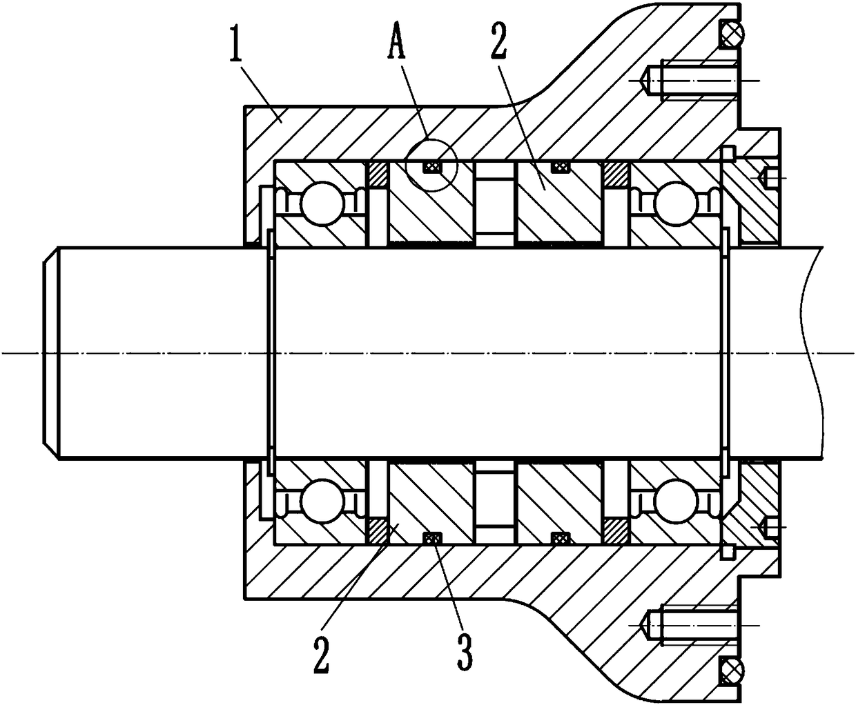
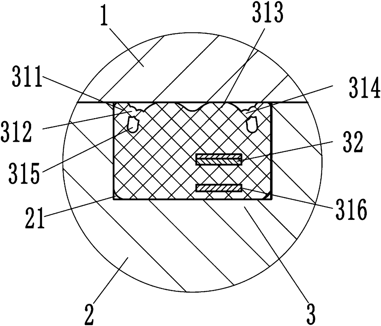
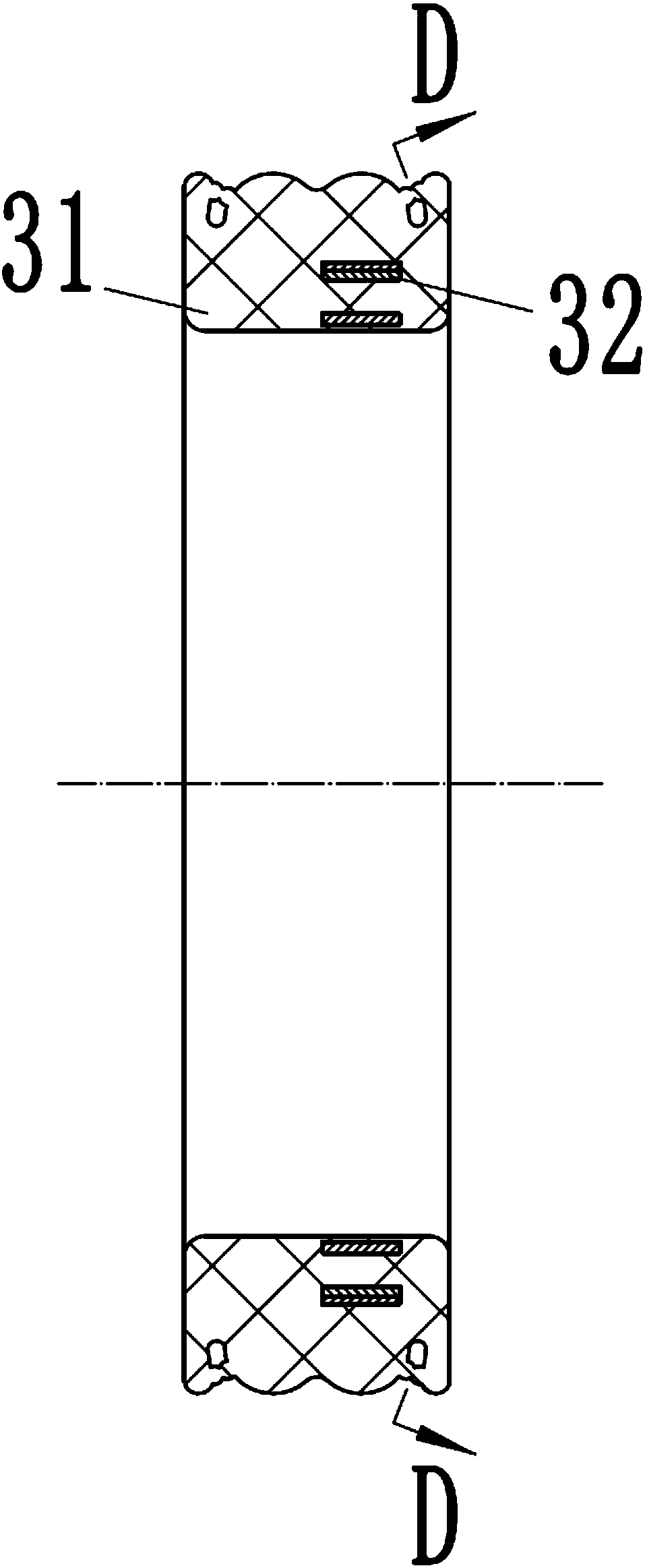
[0028] refer to Figure 1 to Figure 6 ,like figure 1 and image 3 The shown dynamic sealing device for an electrical switch includes: a housing 1, a pair of magnetic poles 2 and a pair of sealing rings 3, the magnetic poles 2 are fitted with the inner hole of the housing 1, and the magnetic poles 2 There is an annular sealing groove 21 on the outer surface, and the sealing ring 3 is embedded in the corresponding sealing groove 21. The sealing ring 3 includes...


PUM


Abstract

The invention discloses a dynamic sealing device for an electric switch. The dynamic sealing device for the electric switch comprises a shell, a pair of magnetic poles and a sealing ring, wherein themagnetic poles are matched with an inner hole of the shell; an annular sealing groove is formed in the outer surface of each magnetic pole; and the sealing ring is embedded in the sealing grooves andcomprises a body and a plurality of elastic pieces. Due to the structure, the property of sealing between the magnetic poles and the shell is good.

Description

technical field [0001] The invention relates to a sealing device, in particular to a dynamic sealing device for an electric switch. Background technique [0002] Chinese patent CN200710147638.8 discloses a dynamic sealing device for medium and high voltage power switchgear. The action structure and the main shaft of the outdoor operating mechanism of the inflatable compartment, two bearings for installing the main shaft, at least one permanent magnet or at least two magnetic poles that are installed in cooperation with the inner hole of the housing and have a gap with the main shaft, The two magnetic poles are respectively located on both sides of the permanent magnet, the magnetic poles have a plurality of magnetic pole teeth, and a magnetic fluid is installed between the magnetic pole teeth of the magnetic poles and the main shaft, wherein the outer circles of the two magnetic poles A first sealing ring is installed on the top to ensure static sealing. [0003] The seali...

Claims


Application Information

Patent Timeline
Patent Type & Authority Applications(China)
IPC IPC(8): H01H9/04
CPCH01H9/04
Inventor 张才华
Owner ZHEJIANG IND & TRADE VACATIONAL COLLEGE
Why Eureka
Try Eureka