Robot with over-obstacle function

A robot and functional technology, applied in the field of robots with obstacle crossing function, can solve the problems of cumbersome equipment, time-consuming and labor-intensive, and low work efficiency.

Pending Publication Date: 2018-08-24
SUZHOU UNIV OF SCI & TECH
View PDF0 Cites 4 Cited by
  • Summary
  • Abstract
  • Description
  • Claims
  • Application Information

AI Technical Summary

Problems solved by technology

[0003] The technical problem to be solved by the present invention is: in order to solve the detection of the pipeline by the existing equipment, since the pipeline and the pipeline are connected through the flange plate protruding outward, when the equipment encounters the flange plate between the pipelines, it needs to

Method used


Image

  • Robot with over-obstacle function
  • Robot with over-obstacle function
  • Robot with over-obstacle function

Examples


Embodiment

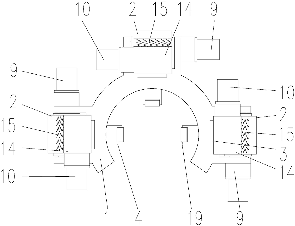
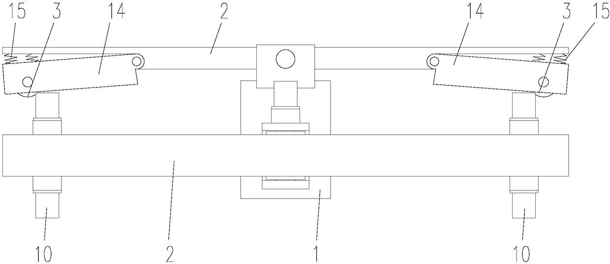
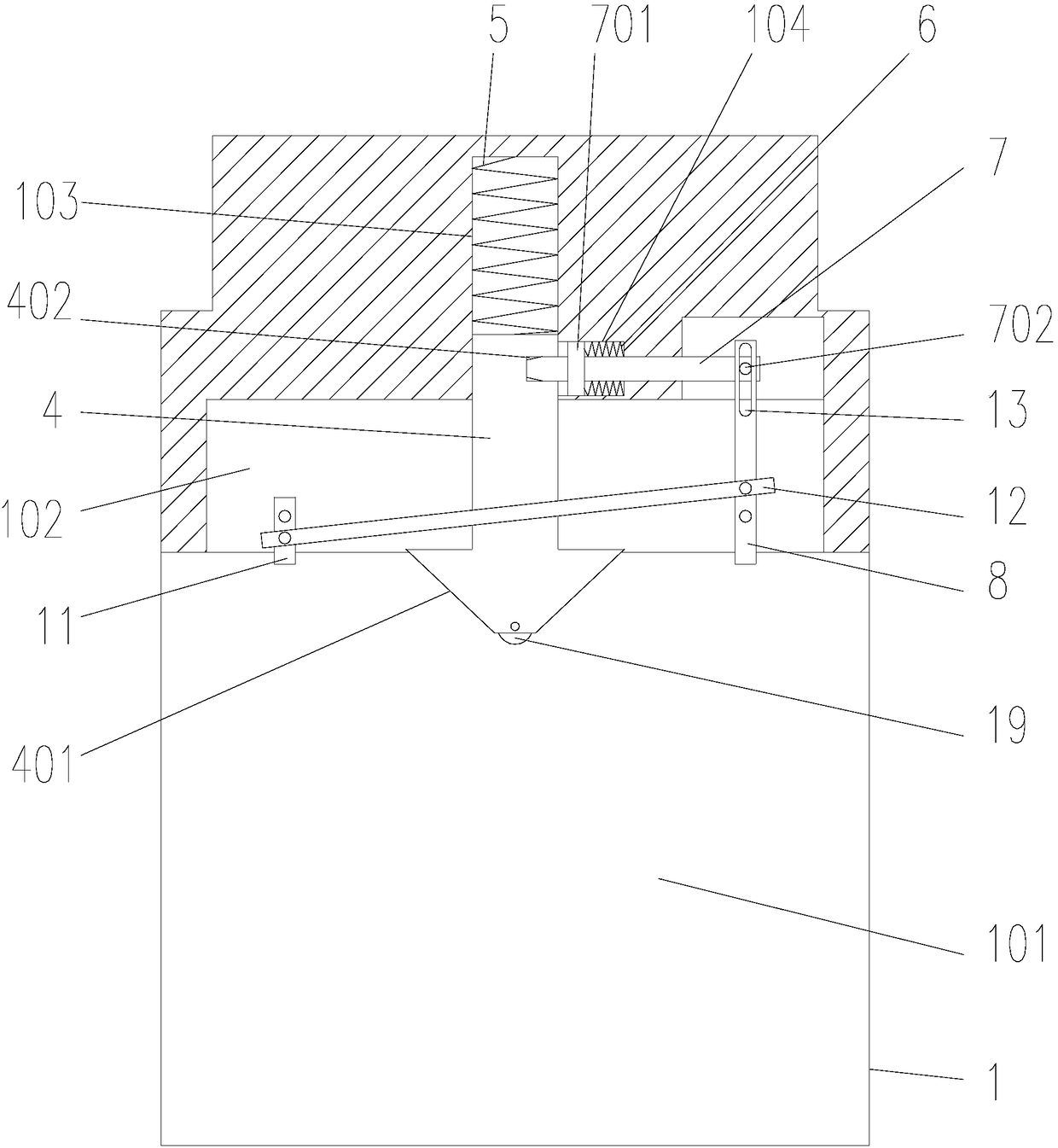
[0024] like Figure 1-9Shown, a kind of robot with obstacle-surmounting function, comprises base 1, connecting rod 2, roller 3, support plate 4, first spring 5, second spring 6, limit column 7 and first bar 8, described The connecting rod 2 is rotatably arranged on the base 1, the base 1 is provided with a first motor 9 for driving the connecting rod 2 to swing, and the two ends of the connecting rod 2 are provided with the rollers 3, so The connecting rod 2 is provided with a second motor 10 for driving the roller 3 to rotate, the first motor 9 is fixedly connected to the base 1, and the output of the first motor 9 is connected by transmission between the connecting rods 2, and the connecting rod 2 The center of rotation is located between the rollers 3 at both ends of the connecting rod 2, that is, the base 1 is located between the rollers 3 at both ends of the connecting rod 2, and the base 1 is provided with a notch 101 along the length direction of the connecting rod 2, ...


PUM


Abstract

The invention relates to the technical field of robot equipment, in particular to a robot with an over-obstacle function. The robot with the over-obstacle function comprises a base, connecting rods, rollers, support plates, first springs, second springs, limiting columns and first rods. The connecting rods are rotatably arranged on the base, the base is provided with first motors for driving the connecting rods to swing, the rollers are arranged at the two ends of the connecting rods, and the connecting rods are provided with second motors for driving the rollers to rotate. The robot with theover-obstacle function is supported on a pipe through the support plates on the base during use, the reciprocating swing of the connecting rods is controlled at the same time, the rollers at one endsof the connecting rods are connected to the pipe so as to control the robot to walk on the pipe, when the robot overs an obstacle, the first rods are in contact with flange plates to drive the limiting columns to be separated from clamping grooves, at the same time, the flange plates act on the inclined surfaces of the support plates, so that the support plates are risen, and the base passes through the flange plates.

Description

technical field [0001] The invention relates to the technical field of robot equipment, in particular to a robot with an obstacle-surmounting function. Background technique [0002] In some special occasions, it is necessary to use the pipeline to transport the medium for a long distance. In order to facilitate the maintenance of the staff, the pipeline is detected through the existing equipment. For the flange between the pipes, it is necessary to manually place the equipment on the other end of the pipe and then inspect the pipe. In some large-diameter pipes, the equipment used is relatively cumbersome, and manual transfer is time-consuming and labor-intensive, and the work efficiency is low. Contents of the invention [0003] The technical problem to be solved by the present invention is: in order to solve the detection of the pipeline by the existing equipment, since the pipeline and the pipeline are connected through the flange plate protruding outward, when the equip...

Claims


Application Information

Patent Timeline
IPC IPC(8): B62D57/02
CPCB62D57/02E02B17/0034
Inventor 钱蜜林维甜陆文浩张子晔仇新凯张明敏王敏杰魏贤伟李逸凡
Owner SUZHOU UNIV OF SCI & TECH
Why Eureka
Try Eureka