
Self-pressure reducing type wire coil device

A wire reel and reel plate technology, which is applied in the field of self-decompression wire reel devices, can solve the problems of increased pressure on the lower part of the wire reel device, equipment damage, etc., and achieve the effect of tight winding

Inactive Publication Date: 2018-08-24
郑序
View PDF8 Cites 6 Cited by
  • Summary
  • Abstract
  • Description
  • Claims
  • Application Information

AI Technical Summary

Problems solved by technology

[0002] At present, the main function of the wire reel device is to wind wires, cables, etc. on the cylinder. The wire reel device in the prior art is often just a simple straight cylinder winding. The more, coupled with the effect of gravity, the lower pressure of the wire reel device will become larger, which will easily cause equipment damage

Method used


Image

  • Self-pressure reducing type wire coil device
  • Self-pressure reducing type wire coil device
  • Self-pressure reducing type wire coil device

Examples


Embodiment Construction

[0017] The following will clearly and completely describe the technical solutions in the embodiments of the present invention with reference to the accompanying drawings in the embodiments of the present invention. Obviously, the described embodiments are only some, not all, embodiments of the present invention.

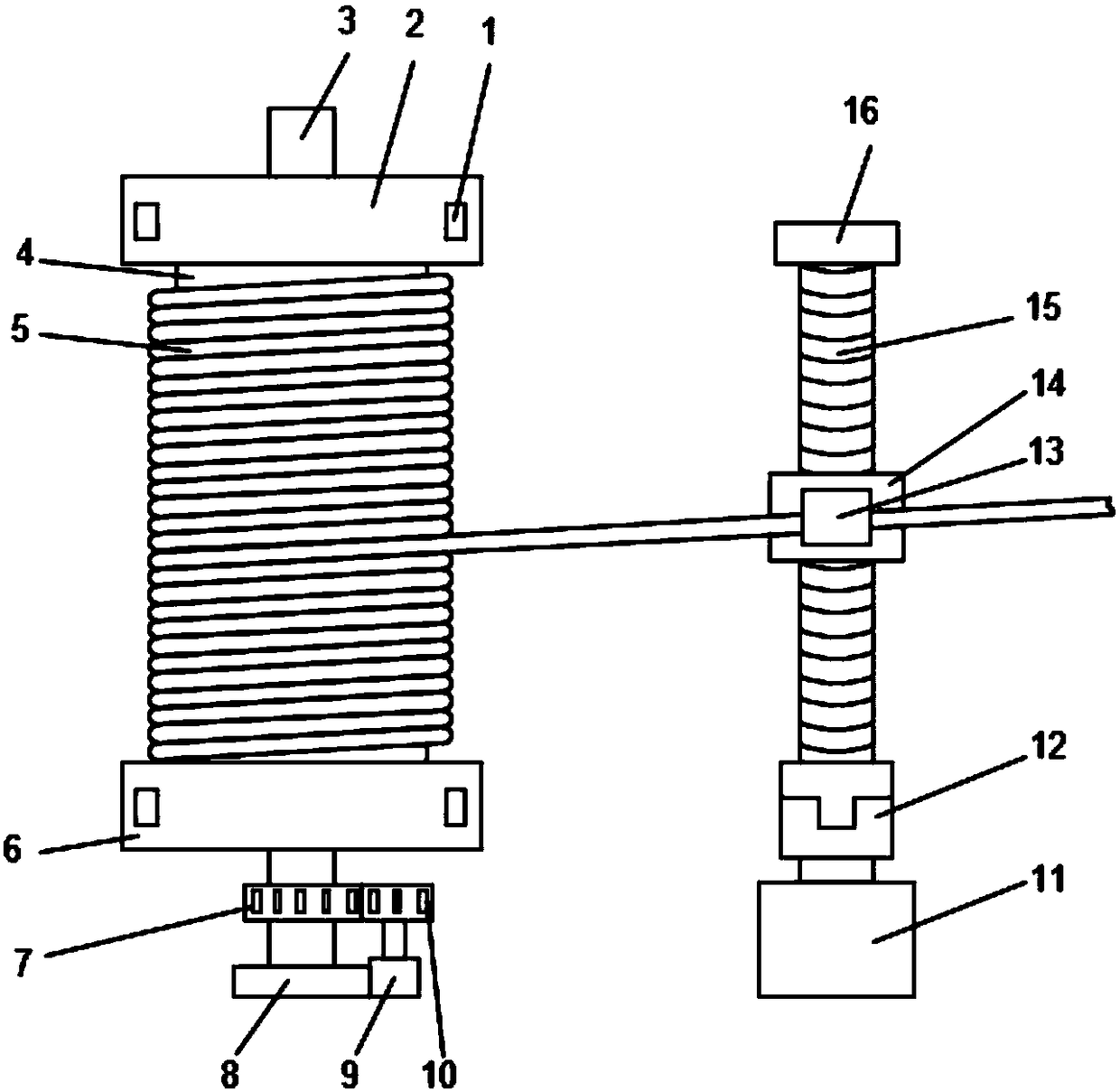
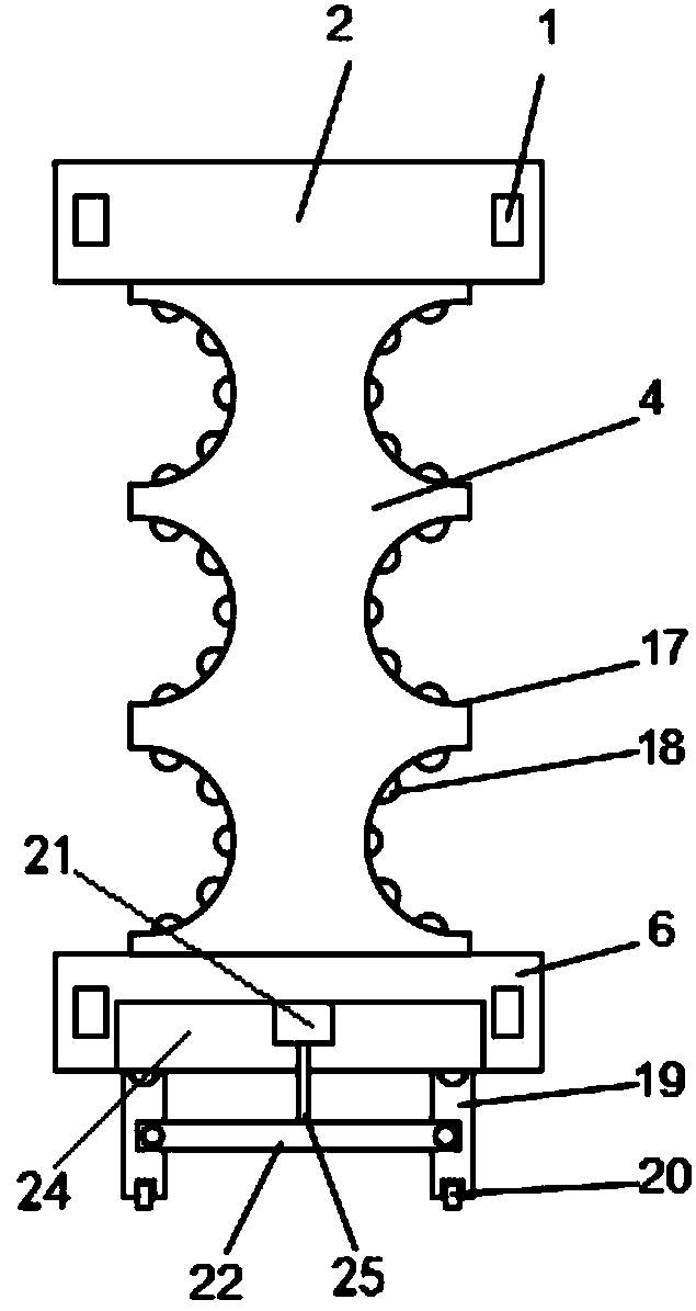
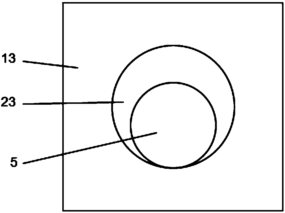
[0018] refer to Figure 1-3 , a self-decompression reel device, comprising a bobbin 4, the bobbin 4 is a hollow structure, the side wall of the bobbin 4 is provided with a plurality of arc-shaped winding grooves 17, and a plurality of arc-shaped winding grooves The inner side walls of 17 are all fixedly connected with a plurality of evenly distributed rubber blocks 18, so that the winding wire 5 will not produce too much pressure on the bobbin 4 when it is carried out, and it has certain elasticity. The upper end of the bobbin 4 is fixedly connected with The upper plate 2 and the lower end of the bobbin 4 are fixedly connected with the lower plate 6, and the side wal...


PUM


Abstract

The invention discloses a self-pressure reducing type wire coil device. The self-pressure reducing type wire coil device comprises a winding reel which is of a hollow structure. The side wall of the winding reel is provided with a plurality of arc-shaped winding grooves. The upper end of the winding reel is fixedly connected with an upper disk plate, and the lower end of the winding reel is fixedly connected with a lower disk plate. A rotating rod is inserted into the winding reel. The two ends of the rotating rod penetrate the lower side wall of the upper disk plate and the upper side wall ofthe lower disk plate correspondingly and extend. The lower end of the rotating rod is provided with a plane bearing. The part, located between the lower disk plate and the plane bearing, of the rotating rod is sleeved with a driven gear. A gear motor is arranged below the lower disk plate. The drive end of the speed reducing motor is fixedly connected with a drive gear. According to the self-pressure reducing type wire coil device, due to the fact that the multiple arc-shaped winding grooves are formed, when a winding wire is wound, pressure is only exerted on the lower portion of the windingreel, the pressure can be dispersed to the side wall of the winding reel, self-pressure reducing treatment is achieved, and winding is tighter.

Description

technical field [0001] The invention relates to the technical field of wire reels, in particular to a self-decompression type wire reel device. Background technique [0002] At present, the main function of the wire reel device is to wind wires, cables, etc. on the cylinder. The wire reel device in the prior art is often just a simple straight cylinder winding. The more, coupled with the effect of gravity, the lower pressure of the wire reel device will become larger, which will easily cause equipment damage. [0003] For this reason, we propose a kind of self-depressurization type coil device to solve the above-mentioned problem. Contents of the invention [0004] The purpose of the present invention is to solve the shortcomings in the prior art, and propose a self-decompression type wire reel device. The present invention sets a plurality of arc-shaped winding grooves, so that when the winding wire is wound, it will not only exert pressure on the bottom of the bobbin, ...

Claims


Application Information

Patent Timeline
IPC IPC(8): B65H54/28B65H54/44B65H54/54B65H75/26
CPCB65H54/2818B65H54/44B65H54/54B65H75/265B65H2701/34
Inventor 郑序
Owner 郑序
Learn More