Deformation seam template support method

A technology of deformation joints and formwork, which is applied in the fields of formwork/formwork/work frame, on-site preparation of building components, construction, etc., can solve the problems of prolonged construction period, material waste, repeated surface trimming, etc., to save materials and shorten the Simple and convenient effect of construction period, support and dismantling

Active Publication Date: 2020-08-04
CHINA AEROSPACE CONSTR GROUP +1
View PDF1 Cites 0 Cited by
  • Summary
  • Abstract
  • Description
  • Claims
  • Application Information

AI Technical Summary

Problems solved by technology

The above construction methods are likely to cause waste of materials and prolong the construction period, which runs counter to the concept of green construction
At the same time, the construction quality of the above method is not easy to control, and the surface needs to be repeatedly trimmed
If the polystyrene board is filled, there is still the disadvantage that the polystyrene board cannot be removed or is not easy to remove and clean

Method used


Image

  • Deformation seam template support method
  • Deformation seam template support method
  • Deformation seam template support method

Examples


Embodiment 1

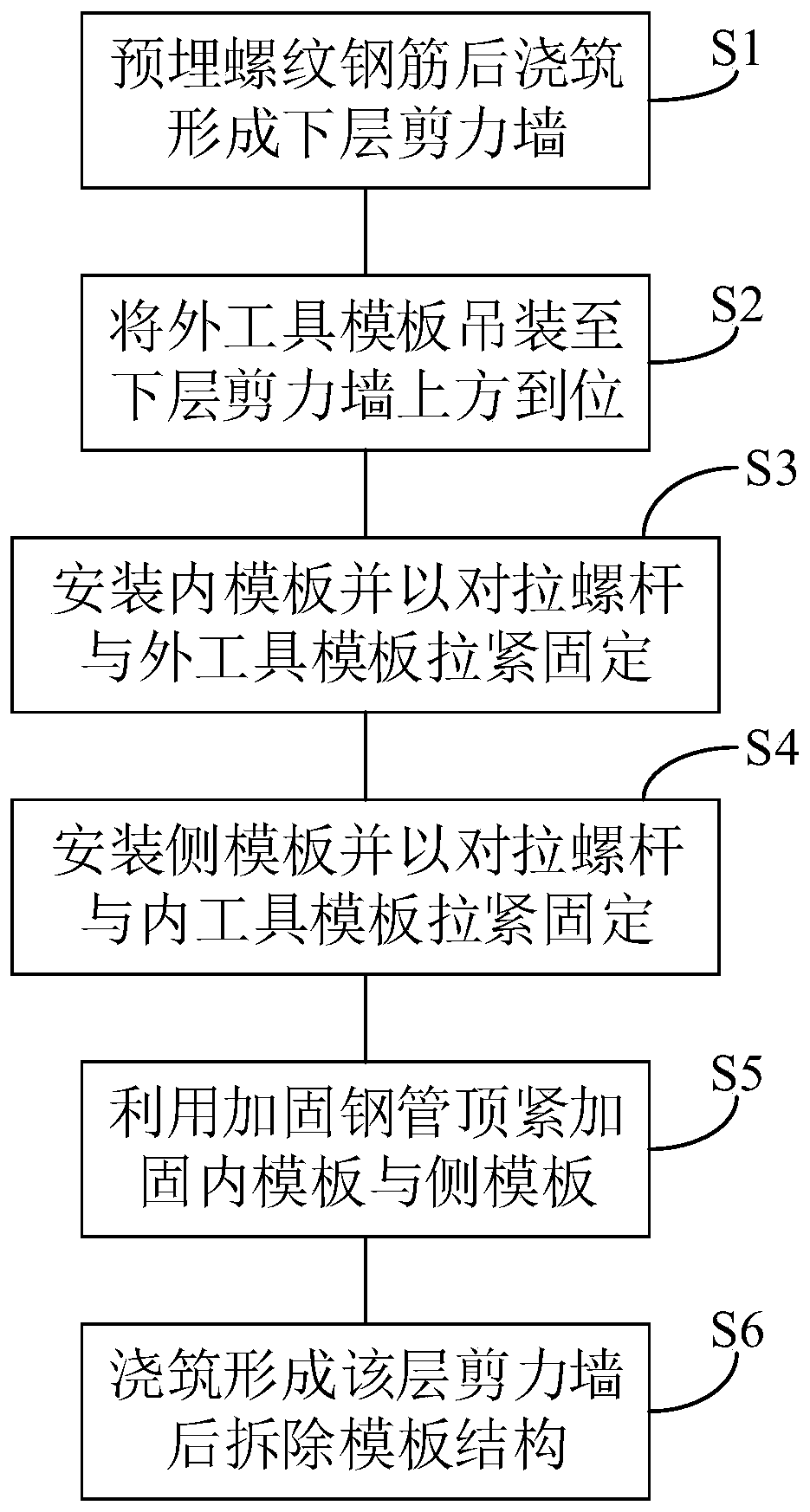
[0036] see Figure 1~5 , this embodiment discloses a method for supporting a deformation joint template, which is used to support a deformation joint with a turning structure, including the following steps:

[0037] S1: Concrete is poured after embedding multiple threaded steel bars to form the lower shear wall. When pre-embedding, the threaded steel bars are distributed high outside and low inside.

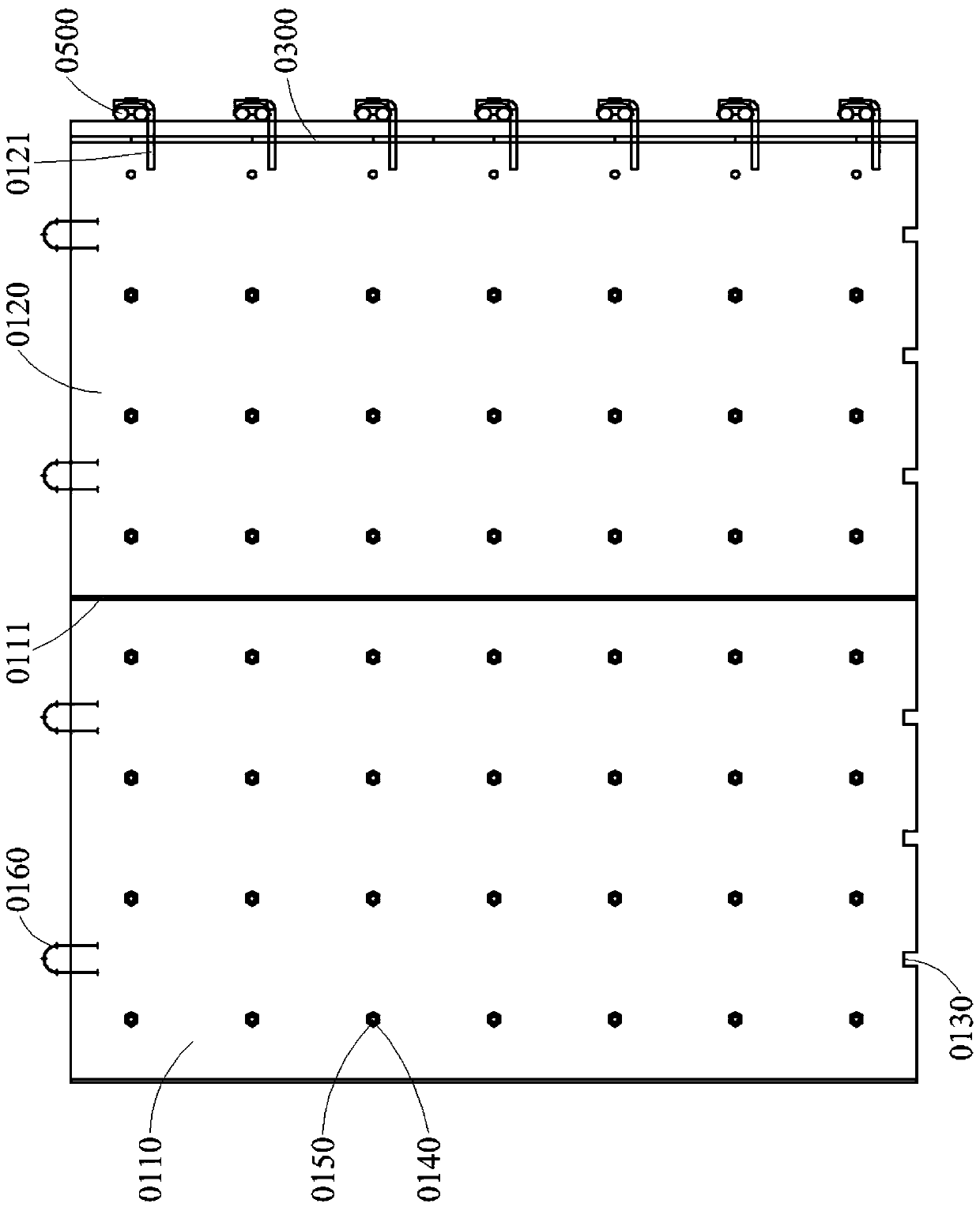
[0038] S2: Hoist the outer tool formwork 0100 above the lower shear wall, so that the support groove 0130 and the threaded steel bar are snapped into place. Exemplarily, when the outer tool formwork 0100 is spliced ​​by a plurality of plates (for example, a shaped plate 0110 and a non-shaped plate 0120), the multiple plates should be hoisted one by one to the corresponding positions on the upper surface of the lower shear wall, so that each The plates are aligned and clamped with the threaded steel bars respectively. Furthermore, the tongue-and-groove 0111 between adjacent pla...

Embodiment 2

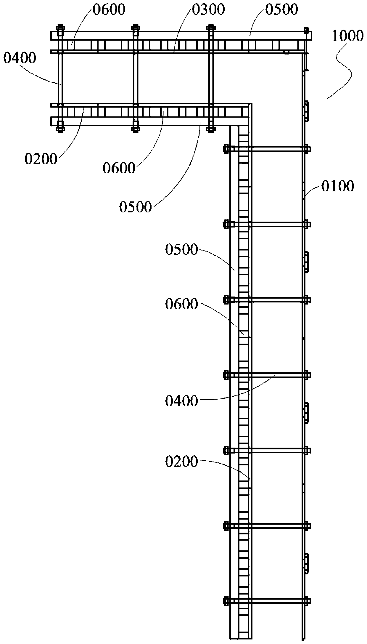
[0046] Please refer to Figure 2~4 , this embodiment further discloses a deformation seam formwork structure 1000, which is used to implement the deformation seam formwork supporting method introduced in Embodiment 1. The deformation seam template structure 1000 includes an outer tool template 0100, an inner template 0200, and a side template 0300 arranged at one end of the outer tool template 0100. The outer tool template 0100 and the side template 0300 are connected to form the outer surface of the deformation seam, and the inner template 0200 is used to form The inner surface of the deformation seam.

[0047] For example, in the application of deformation joints with an L-shaped structure, the inner template 0200 is spliced ​​to form the inner surface of the L-shaped structure, and the outer tool template 0100 is connected with the side template 0300 to form the outer surface of the L-shaped structure. It can be understood that the inner template 0200 can be formed by spli...


PUM


Abstract

The invention discloses a deformation joint template erecting method. The deformation joint template erecting method comprises the following steps that a plurality of thread steel bars is embedded andconcrete is poured to form a lower layer shear wall; an external tool template is hoisted to the upper part of the lower layer shear wall, the external tool template is aligned with the thread steelbars and the external tool template and the thread steel bars are connected in position in a clamping mode; an internal template is installed at a corresponding position according to the elevation ofa shear wall axis, and tensioning and fixation are realized by an opposite-pull screw and the external tool template; a side template is installed to a corresponding position according to the elevation of the shear wall axis, and tensioning and fixation are realized by an opposite-pull screw and the internal template; the ejecting and strengthening of the internal template and the side template are carried out by using strengthened steel pipes; and the external tool template is separated from a wall and hoisted away after casting and forming the shear wall of the layer, and the removal is completed. The deformation joint template erecting method realizes the simultaneous construction of shear walls on both sides of a deformation joint, is simple and convenient to erect and dismantle, and can effectively save materials and shorten the construction period.

Description

technical field [0001] The invention belongs to the technical field of construction engineering, and specifically relates to a method for supporting a deformation joint formwork. Background technique [0002] In the existing formwork support construction of deformation joints, the shear wall on one side is generally constructed first, and then the shear wall on the other side is constructed; or polystyrene boards are filled in the deformation joints. The above-mentioned construction methods are likely to cause waste of materials and prolong the construction period, which runs counter to the concept of green construction. At the same time, the construction quality of the above method is not easy to control, and the surface needs to be repeatedly repaired. If the polystyrene board is filled, there is also the disadvantage that the polystyrene board cannot be removed or is not easy to remove and clean. Contents of the invention [0003] In order to overcome the deficiencies...

Claims


Application Information

Patent Timeline
Patent Type & Authority Patents(China)
IPC IPC(8): E04G11/08
CPCE04G11/08
Inventor 冯庆飞朱超峰李雷于兵兵张军涛姚川秦
Owner CHINA AEROSPACE CONSTR GROUP
Why Eureka
Try Eureka