
Touch position prompt method and controlled equipment

A controlled device and touch position technology, applied in the direction of instruments, electrical digital data processing, data processing input/output process, etc., can solve the problem of high misjudgment rate, poor user experience, and inability to distinguish which cursor on the controlled device and other issues to achieve the effect of improving positioning speed and accuracy and improving user experience

Inactive Publication Date: 2018-08-24
BEIJING YINGKE TECH CO LTD
View PDF6 Cites 4 Cited by
  • Summary
  • Abstract
  • Description
  • Claims
  • Application Information

AI Technical Summary

Problems solved by technology

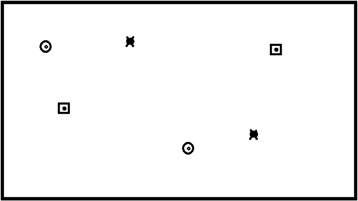
[0002] In the related art, in the scenario where multiple control devices control a controlled device at the same time, the controlled device needs to display the prompt mark of each control device, but in the related art, the same prompt mark is usually used for the prompt marks of multiple control devices , although this display method is simple, it will make it impossible for users to quickly find the prompt mark of their own control device on the controlled device, resulting in a high false positive rate and poor user experience
[0003] For example, in a game device, since the cursors corresponding to different gamepads on the controlled device are the same, it is impossible for the user to distinguish which cursor on the controlled device is his own, and it is necessary to move the gamepad multiple times to observe the controlled device. Judging by the movement of the cursor on the screen, the misjudgment rate is high and the user experience is poor

Method used


Image

  • Touch position prompt method and controlled equipment
  • Touch position prompt method and controlled equipment
  • Touch position prompt method and controlled equipment

Examples


Embodiment Construction

[0073] Reference will now be made in detail to the exemplary embodiments, examples of which are illustrated in the accompanying drawings. When the following description refers to the accompanying drawings, the same numerals in different drawings refer to the same or similar elements unless otherwise indicated. The implementations described in the following exemplary examples do not represent all implementations consistent with the present invention. Rather, they are merely examples of apparatuses and methods consistent with aspects of the invention as recited in the appended claims.

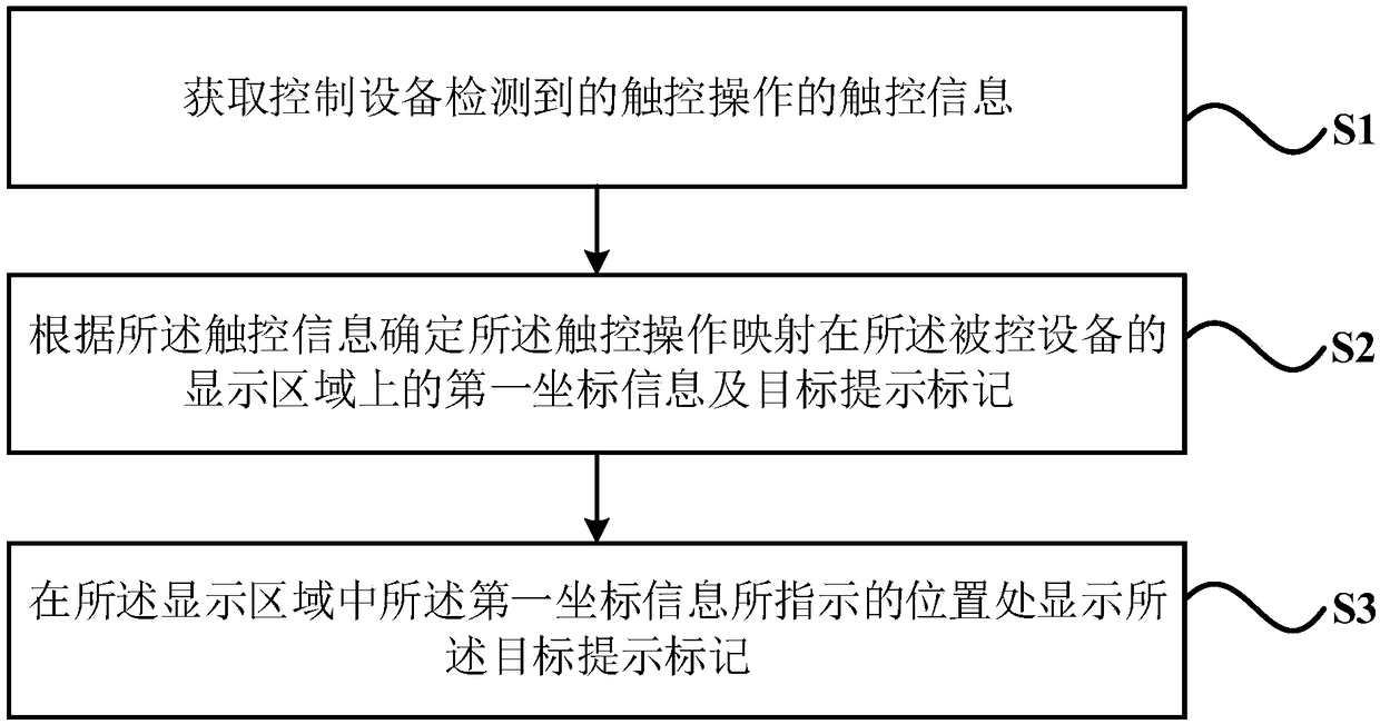
[0074] figure 1 It is a flow chart of a touch position prompting method shown according to an exemplary embodiment, as shown in figure 1 As shown, the method is applied to the controlled device, including the following steps:

[0075] Step S1, acquiring touch information of touch operations detected by the control device;

[0076] Step S2, determining first coordinate information and a target...


PUM


Abstract

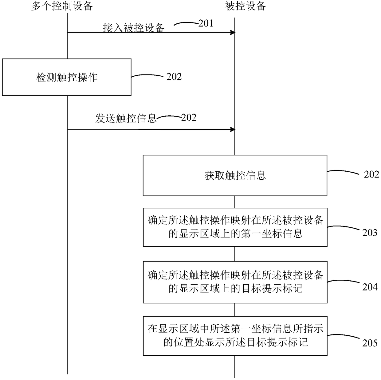
The invention relates to a touch position prompt method and controlled equipment. The method is applied in the controlled equipment, and comprises the following steps of: obtaining touch operation ofa touch operation detected by control equipment; determining first coordinate information, mapped on a display area of the controlled equipment, of the touch operation and a target prompt sign according to the touch information; and displaying the target prompt sign at a position indicated by the first coordinate information in the display area. According to the method, different touch operationsdetected by control equipment are endowed with different target prompt signs, and the target prompt signs are displayed on display areas of controlled equipment, so that users can correctly and rapidly know a position, on the controlled equipment, of each touch operation, the positioning speed and correctness of the users can be improved and then the user experience is enhanced.

Description

technical field [0001] The invention relates to the technical field of intelligent control of display devices, in particular to a touch position prompting method and a controlled device. Background technique [0002] In the related art, in the scenario where multiple control devices control a controlled device at the same time, the controlled device needs to display the prompt mark of each control device, but in the related art, the same prompt mark is usually used for the prompt marks of multiple control devices , although this display method is simple, it will make it impossible for the user to quickly find the prompt mark of his control device on the controlled device, resulting in a high rate of misjudgment and poor user experience. [0003] For example, in a game device, since the cursors corresponding to different gamepads on the controlled device are the same, it is impossible for the user to distinguish which cursor on the controlled device is his own, and it is nece...

Claims


Application Information

Patent Timeline
Patent Type & Authority Applications(China)
IPC IPC(8): G06F3/0488G06F3/0481
CPCG06F3/0481G06F3/0488
Inventor 林行杜頔康
Owner BEIJING YINGKE TECH CO LTD
Learn More