Catheterization device for urological surgery

A technology used in urology and surgery, applied in the direction of catheters, balloon catheters, hypodermic injection devices, etc., can solve the problems of troublesome catheterization, pain and discomfort, etc., and achieve convenient control, pain relief, and convenient use Effect

Active Publication Date: 2018-08-28
THE FIRST AFFILIATED HOSPITAL OF HENAN UNIV OF SCI & TECH
View PDF4 Cites 4 Cited by
  • Summary
  • Abstract
  • Description
  • Claims
  • Application Information

AI Technical Summary

Problems solved by technology

However, in the process of the catheter entering the body, such as in the male urethra, there is a bend position, and when the catheter head or catheter passes through this bend, it

Method used


Image

  • Catheterization device for urological surgery
  • Catheterization device for urological surgery
  • Catheterization device for urological surgery

Examples


Embodiment 1

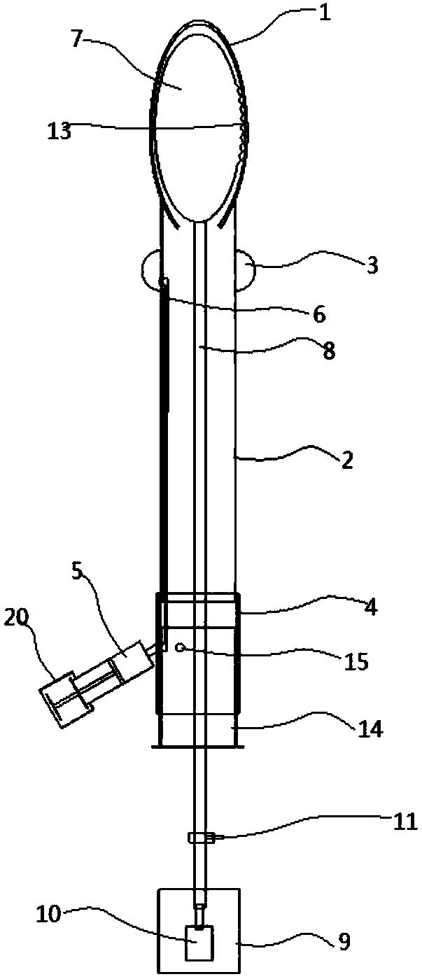
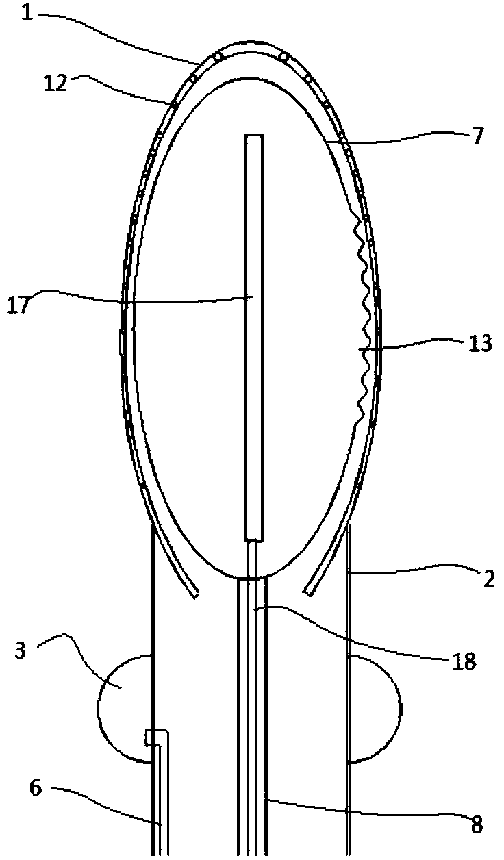
[0026] Embodiment 1, when the present invention is in use, the water pump 9 pressurizes and fills the control airbag 7 for the initial expansion, and realizes positioning and fitting in the catheter head 1, and the medical staff inserts the catheter head 1 and the catheter 2 into the urethra, And the initial position makes the bending direction after expansion adapt to the direction of the curve in the urethra. The medical staff can judge whether the catheter head 1 can reach the curve according to experience and resistance. Continue to pressurize and fill the water, and the uneven axial expansion length of the control airbag 7 leads to bending, so that the attached urinary catheter head 1 follows the bending, and then can pass through the curve smoothly. After passing, the liquid is discharged to make the control airbag 7 contract and recover. After the catheter head 1 reaches the designated position in the body, the syringe 5 is used to inflate the positioning air bag 3 to re...

Embodiment 2

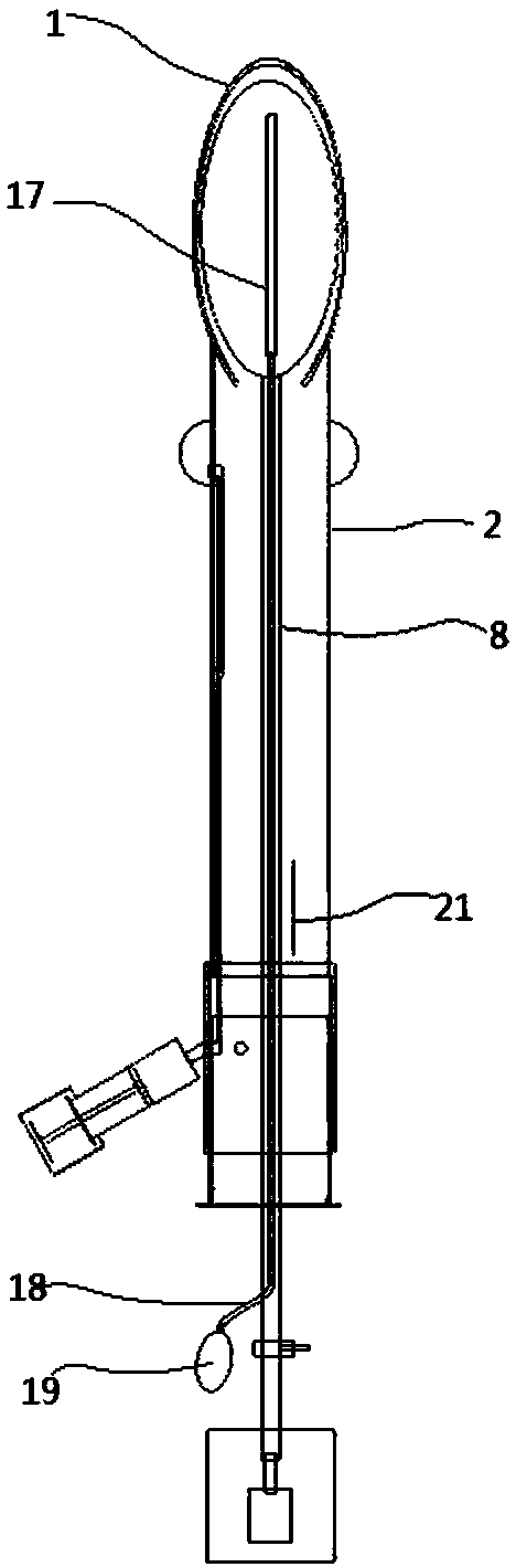
[0027] Embodiment 2, by controlling the communication of the syringe 5 through the control tube 14, when the syringe 5 communicates with the inflation tube 6 through a docking hole 15, the positioning airbag 3 can be inflated to make it inflated and positioned; turn the control tube 14 to disconnect The syringe 5 communicates with the inflatable tube 6, and the control tube 14 and the connecting tube 4 are rotated and sealed, and the inflatable tube 6 communicates with the docking hole 15 in a sealed state, and then the other docking hole 15 is connected to the output port of the syringe 5 , then the inside of the urinary catheter 2 is connected with the syringe 5. At this time, it is convenient to carry out work such as pumping / exhausting, liquid, etc., and when the port of the control tube 14 is sealed with the sealing cap 16, the syringe 5 can be used to extract the urinary catheter 2 The liquid inside forms a negative pressure suction.

[0028] When the urinary catheter he...


PUM


Abstract

The invention discloses a catheterization device for urological surgery, and relates to the technical field of urological surgery. The catheterization device comprises a catheterization head and a catheter; the catheterization head is communicated with the upper end of the catheter in a sealed manner; the upper portion of the outer side of the catheter is sleeved with a positioning air sac; the lower end of the catheter is communicated with a connecting tube; the side edge of the connecting tube is communicated with an injector; the positioning air sac is communicated with an inflating tube; the tail end of the inflating tube is communicated with the output port of the injector in a sealed manner; a control air sac is arranged in the catheterization head; the lower end of the control air sac is communicated with a water guide tube; the tail end of the water guide tube extends to the outside of the connecting tube and is communicated with the output end of a water pump; the water pump is installed in a water tank; a drain valve is installed on the lower portion of the water guide tube; catheterization holes are uniformly formed in the side face of the catheterization head; a telescopic fold part is arranged on one side of the control air sac; after the control air sac expands, the catheterization head wraps the control air sac. The catheterization device has the advantages thatthe device can be bent under active control at the urethra bend to pass through the bend smoothly, and thus pain is relieved.

Description

technical field [0001] The invention relates to the technical field of urology. Background technique [0002] When performing catheterization work on urological patients, the catheterization device is used to connect with the patient's body to achieve catheterization. However, in the process of the catheter entering the body, such as in the male urethra, there is a bend position, and when the catheter head or catheter passes through this bend, it cannot pass smoothly, causing pain and discomfort, which is harmful to catheterization. The placement of the device presents a hassle that is not addressed by conventional catheterization devices. Contents of the invention [0003] The technical problem to be solved by the present invention is to provide a urinary catheterization device for urological surgery aiming at the above technical deficiencies. Actively controlled bending can be performed at the urethral bend, passing through the bend smoothly and reducing pain. [0004...

Claims


Application Information

Patent Timeline
IPC IPC(8): A61M1/00A61M25/10
CPCA61M1/0023A61M25/1018A61M2210/1089A61M25/10181A61M25/10182A61M1/84A61M2210/005
Inventor 宋松毅罗冬平
Owner THE FIRST AFFILIATED HOSPITAL OF HENAN UNIV OF SCI & TECH
Why Eureka
Try Eureka