Supercharge Your Innovation With Domain-Expert AI Agents!

Feeder and part feeding device

A feeder and parts technology, which is applied in the field of feeders and parts supply devices, can solve the problems of reduced parts conveying density and achieve the effect of increasing the supply speed

Active Publication Date: 2018-08-28
DAISHIN CO LTD
View PDF9 Cites 2 Cited by
  • Summary
  • Abstract
  • Description
  • Claims
  • Application Information

AI Technical Summary

Problems solved by technology

In such a setting, although the parts are initially conveyed with a high conveying density, a large number of parts are conveyed in a disorderly overlapping posture, so many parts are excluded in the subsequent sorting process, so that the final part P is When conveyed in a line in a standard posture, it becomes a conveying form in which there are many gaps in the conveying direction between the parts P, and the conveying density of the parts is often greatly reduced.

Method used


Image

  • Feeder and part feeding device
  • Feeder and part feeding device
  • Feeder and part feeding device

Examples


Embodiment Construction

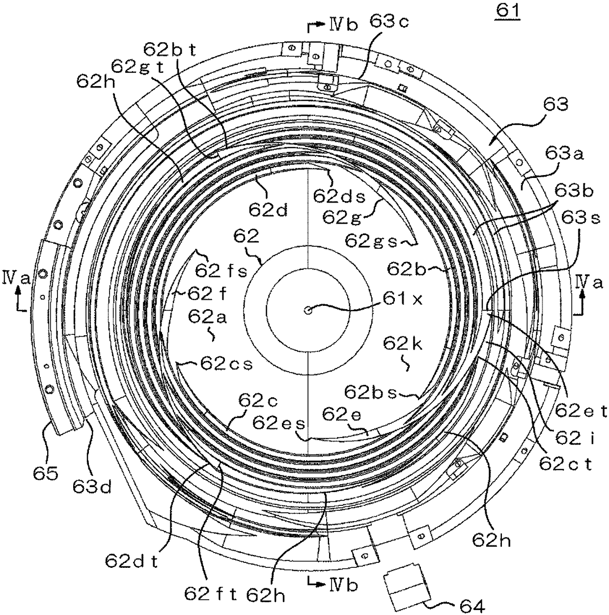
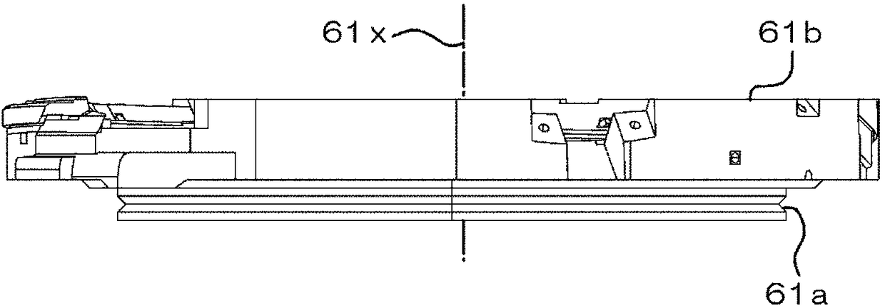
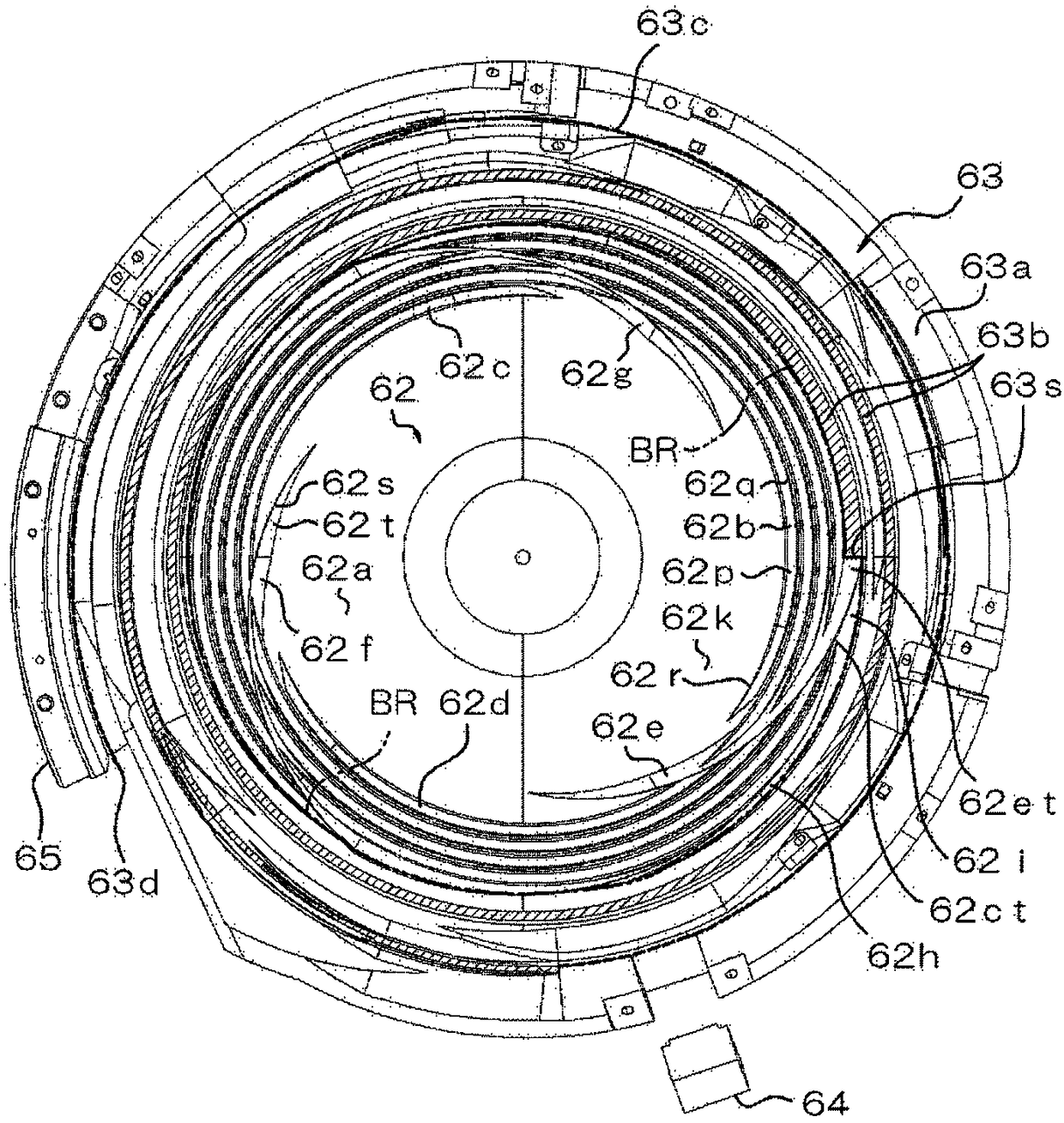
[0058] Hereinafter, embodiments of the present invention will be described in detail with reference to the drawings. First, refer to Figure 1 to image 3 The shape and structure of the conveying body mounted in the embodiment of the feeder according to the present invention, that is, the parts container will be described. In addition, in the description of the following embodiment, the structure of the feeder other than the illustrated components container is considered to be the general structure which mounts the components container on the conventional rotary vibration machine as shown in FIG. 6. In addition, the structure of the parts supply apparatus including a feeder is the same as above. Here, descriptions of generally employable configurations as described above are omitted.

[0059] The parts container 61 according to the embodiment of the present invention can be integrally provided using metals such as aluminum and an aluminum alloy, or other materials. However, i...


PUM


Abstract

An objective of the invention is to improve supply speed of parts. A feeder has a component holding device (61) and a rotary vibration machine that makes the periphery of the axis of the component holding device rotate and vibrate. The component holding device (61) has an inner bottom (62) and an inner peripheral portion (63). The inner bottom (62) has a cone frustum shaped inner surface (62a), and has component guide grooves (62b, 62c, 62d, 62e, 62f, 62g) formed on the inner surface and extending toward an outer peripheral side. The inner peripheral portion (63) has an inverted truncated coneinner surface (63a) and a component conveying path (63b) which is formed on the inner surface and gradually rises from a landing port (63s) located at a boundary position of the inner bottom portion.The component guide grooves guides the components in a manner that the components are limited in a standard posture.

Description

technical field [0001] The present invention relates to a feeder and a parts supply device, and more particularly to a parts guide structure of a parts container constituting the feeder. Background technique [0002] Normally, as shown in FIG. 6( a ) and FIG. 6( b ), the feeder 4 has a structure in which a bowl-shaped parts container 41 is mounted on a rotary vibrator 40 . The parts holder 41 has an inner bottom 42 and an inner peripheral part 43, wherein the inner bottom 42 has a truncated conical inner surface 42a capable of storing a large number of parts and moving the parts to the outer peripheral side, and the inner peripheral part 43 has a An inverted conical inner surface 43 a of the outer periphery of the bottom 42 . The inner peripheral portion 43 is provided with a parts conveyance path 43b formed in a spiral shape around the axis. When the above-mentioned parts container 41 receives the vibration along the rotation direction around the axis and obliquely upward...

Claims


Application Information

Patent Timeline
IPC IPC(8): B65G47/14
CPCB65G47/1464B65G2201/02B65G27/02B65G47/1421B65G2812/0392
Inventor 古田光神户祐二赤岩诚保苅德善折桥英树山本笃史皆川恭弘木内勇希百濑阳介竹下敦希
Owner DAISHIN CO LTD
Features
  • R&D
  • Intellectual Property
  • Life Sciences
  • Materials
  • Tech Scout
  • Unparalleled Data Quality
  • Higher Quality Content
  • 60% Fewer Hallucinations
Learn More