
Safety-health-environment mark mounting mechanism and mounting device

An installation mechanism, safety and health technology, applied in display devices, markers, instruments, etc., can solve the problems of waste of resources, frequent replacement of safety and health rings, short service cycle, etc., and achieve the effect of facilitating separation and avoiding the risk of climbing operations.

Pending Publication Date: 2018-08-28
GUANGDONG POWER GRID CO LTD +1
View PDF0 Cites 2 Cited by
  • Summary
  • Abstract
  • Description
  • Claims
  • Application Information

AI Technical Summary

Problems solved by technology

[0005] The first purpose of the present invention is to provide a safety and health ring installation mechanism, which solves the technical problems of frequent replacement of safety and health rings, short service life and waste of resources in the prior art

Method used


Image

  • Safety-health-environment mark mounting mechanism and mounting device
  • Safety-health-environment mark mounting mechanism and mounting device
  • Safety-health-environment mark mounting mechanism and mounting device

Examples


Embodiment 1

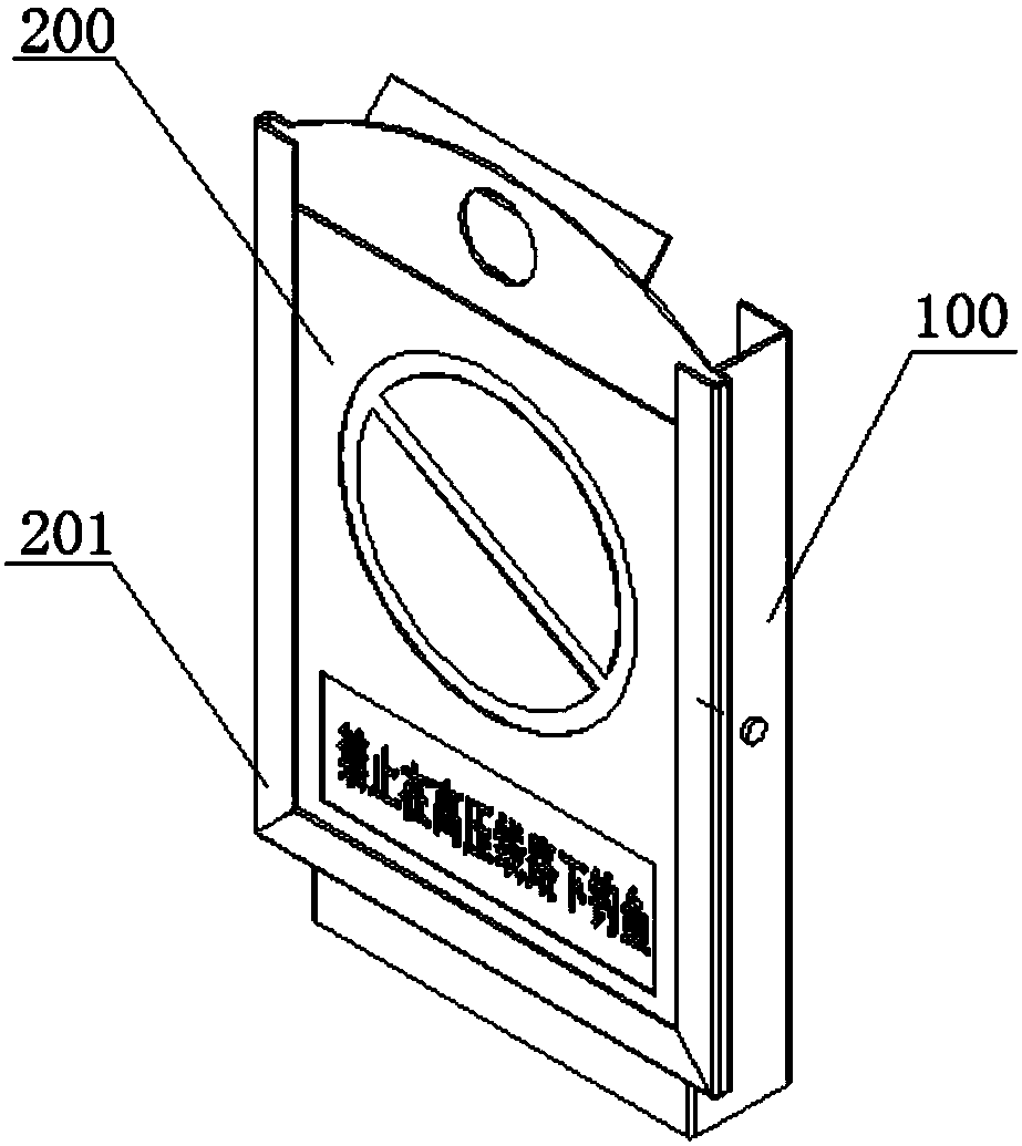
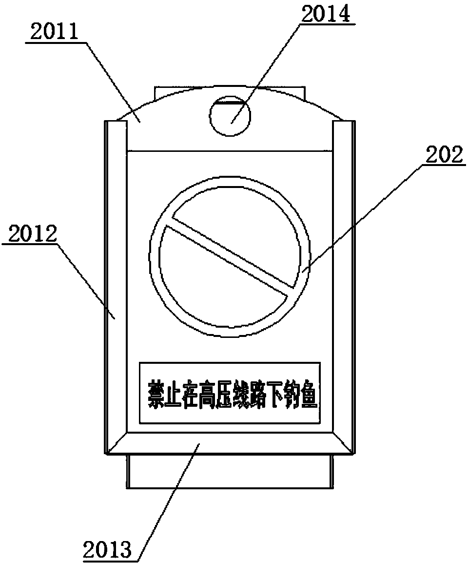
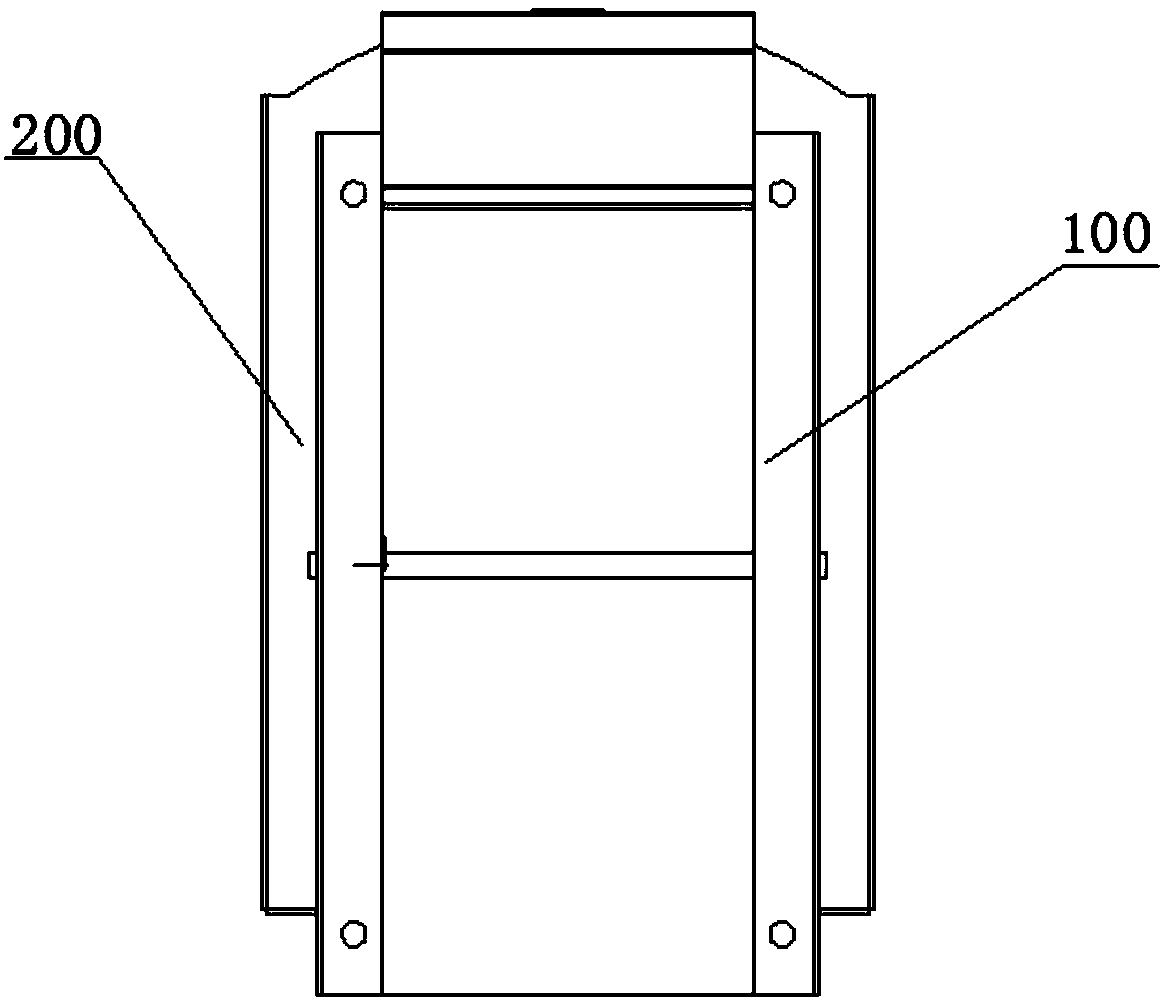
[0041] Such as Figure 1-8 As shown, the safety ring installation mechanism provided by this embodiment includes: a chassis assembly 100 installed on the line and a panel assembly 200 detachably connected to the chassis assembly 100; the panel assembly 200 includes a board body 201 and The indicator board 202 detachably connected with the board body 201, the board body 201 is provided with a buckle 2015; the chassis assembly 100 includes a slot 1013 for buckling with the buckle 2015 and for Lock the locking mechanism of the buckle 2015 .

[0042]Specifically, the chassis assembly 100 includes a frame body 101, and the locking mechanism includes a self-locking fastener 102 and a spring 104; one end of the spring 104 is fixedly connected to the frame body 101, and the other end is connected to the self-locking The fastener 102 is fixedly connected. When the panel assembly 200 is installed on the chassis assembly 100, the buckle 2015 on the panel assembly 200 snaps into the slo...

Embodiment 2

[0055] The installation device provided in this embodiment includes: the above-mentioned safety ring installation mechanism and an insulating rod for installing and dismounting the safety ring installation mechanism, and a hook is arranged on the insulation rod.

[0056] The installation device provided by this embodiment has all the advantages of the above-mentioned safety and health ring installation mechanism due to the setting of the safety and health ring installation mechanism; it solves the technology of frequent replacement of safety and health rings, short service life and waste of resources in the prior art Problem: When using the insulating rod at the same time, the hook on the insulating rod will hook the through hole 2014 on the board body 201, lift the panel assembly 200, and then snap into the card slot 1013 of the chassis assembly 100. During this process, the insulating rod will The hook will push the self-locking fastener 102, and the self-locking fastener 102...


PUM


Abstract

The invention relates to the technical field of mounting of electric power equipment and particularly relates to a safety-health-environment mark mounting mechanism and a mounting device. The safety-health-environment mark mounting mechanism comprises an underframe assembly mounted on lines and a panel assembly detachably connected with the underframe assembly; the panel assembly comprises a platebody and an indicator detachably connected with the plate body, and snapping buckle members are arranged on the plate body; the underframe assembly comprises snapping grooves snapped with the snapping buckle members and locking mechanisms for locking the snapping buckle members. The mounting device comprises the safety-health-environment mark mounting mechanism and an insulating rod for mountingand dismounting the safety-health-environment mark mounting mechanism, and a hanging hook is arranged on the insulating rod. According to the safety-health-environment mark mounting mechanism and themounting device, the technical problems in the prior art that a safety-health-environment mark is frequent in replacement and short in use cycle, resources are wasted, and the risk is high are solved.

Description

technical field [0001] The invention relates to the technical field of installing electric equipment, in particular to a safety and health ring installation mechanism and installation device. Background technique [0002] In the power system, all equipment on the 10kV distribution line has a fixed name and number, and the brand used to display this name and number is called Anjianhuan. The current number plates are all installed in the form of stickers, and the installation position is relatively high from the ground. [0003] In the transformation of power lines, power equipment often changes, such as changing some overhead lines to buried cables. Due to the transformation of distribution network lines every year, the safety and health ring may need to be replaced for each transformation. This replacement generally costs dozens of yuan at least, and hundreds of yuan at most. The cost of each safety and health ring is 100 yuan According to calculations, the cost of replaci...

Claims


Application Information

Patent Timeline
Patent Type & Authority Applications(China)
IPC IPC(8): G09F7/18G09F7/08
CPCG09F7/08G09F7/18G09F2007/1843
Inventor 阮顺添欧少贤范平涛冯颖君黄耀亮谭钰桓陈嘉杰
Owner GUANGDONG POWER GRID CO LTD
Learn More