Connector

A connector and ground connection technology, which is applied in the connection of rods, connecting members, couplings, etc., can solve the problems of device damage and not being used to disassemble the connecting device.

Active Publication Date: 2018-08-31
BARTEC GMBH
View PDF4 Cites 4 Cited by
  • Summary
  • Abstract
  • Description
  • Claims
  • Application Information

AI Technical Summary

Problems solved by technology

[0003] Although it is easier to install the device of WO2010 / 038056, there is no mechanism for detaching the connected device, as would be required for disassembly / maintenance
Disconnecting would require divers (with associated costs and risks) and cause damage to the unit

Method used


Image

  • Connector
  • Connector
  • Connector

Examples


Embodiment Construction

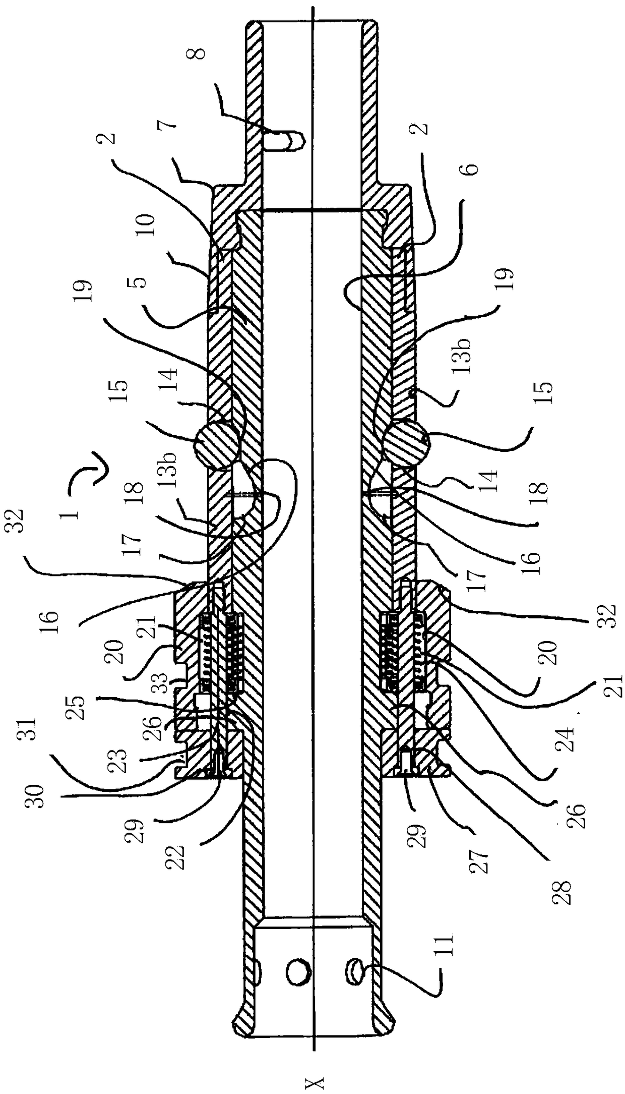
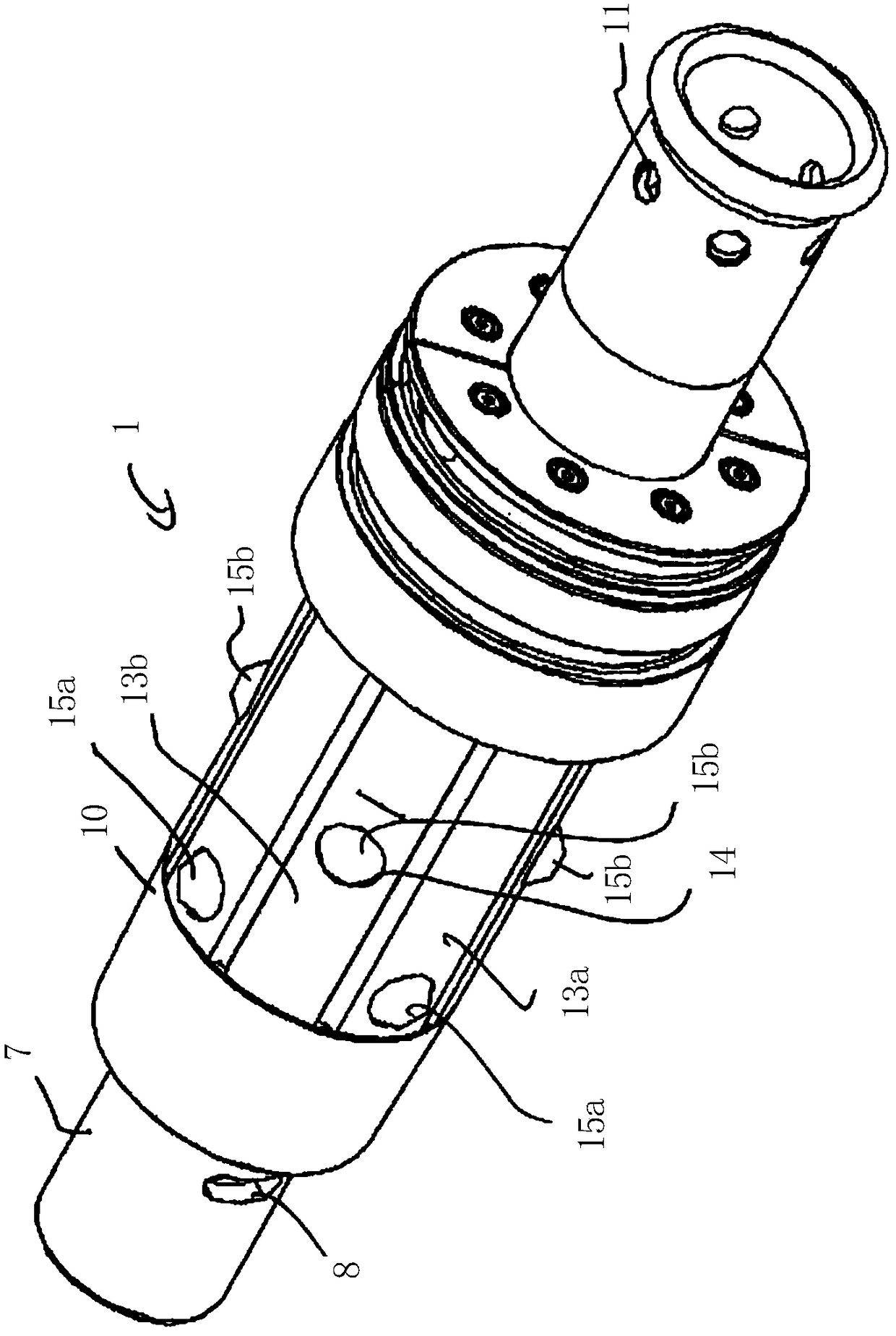
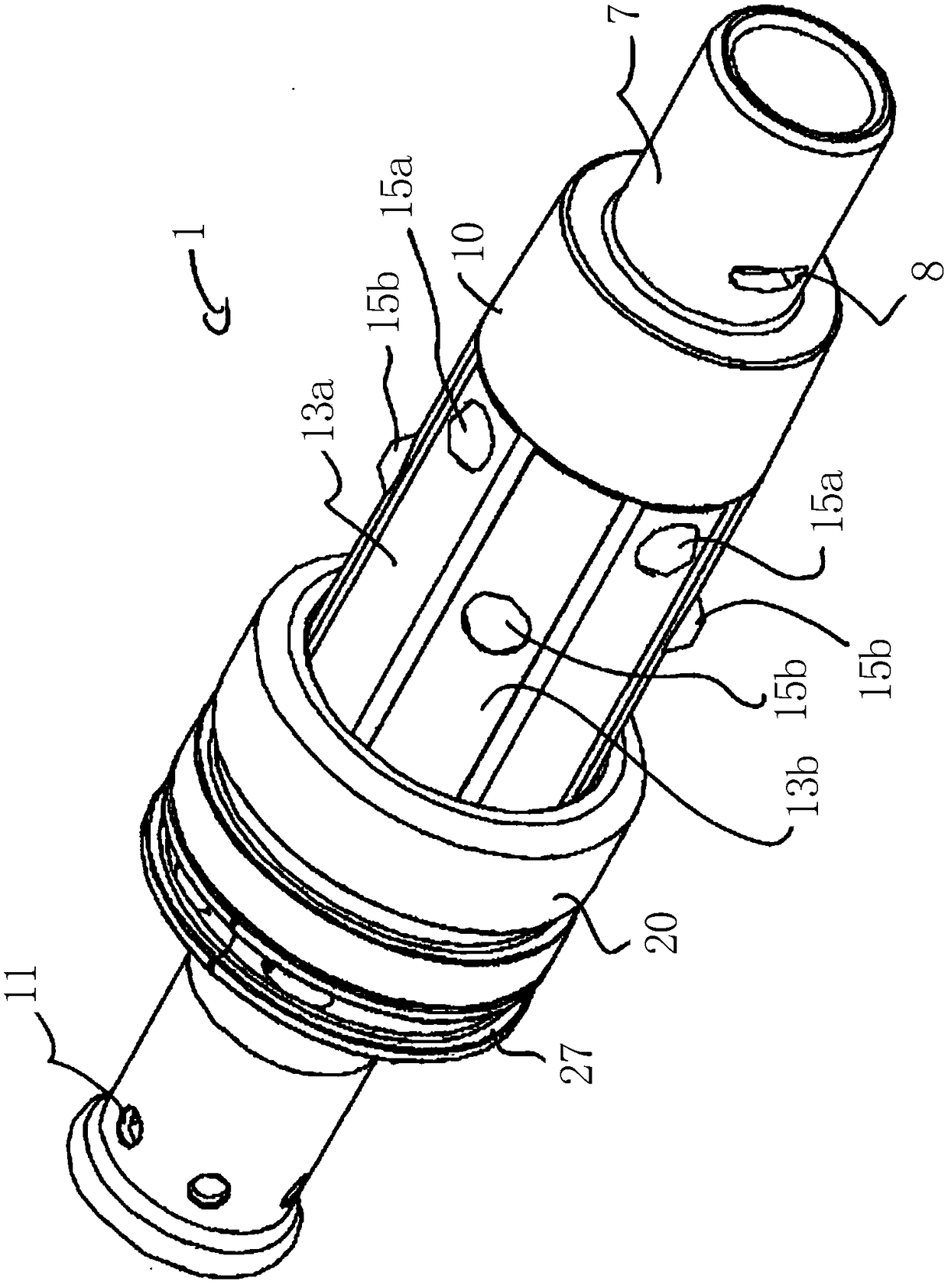
[0090] refer to Figure 1 to Figure 12 , shows a first embodiment of a subsea connector 1 for connecting a cable (not shown) to a support column 3 of a wind turbine generator (such as Figure 4-Figure 7 shown).

[0091] The connector 1 is a male part arranged to be inserted into a female part in the form of a hole 4 extending through the support post 3 at an oblique angle. In an alternative (not shown) the connector may extend into a specially adapted J-tube formed behind (inwardly) the guide cone with a flange acting as the bore.

[0092] The connector 1 comprises a hollow load-bearing mandrel 5 through which a cylindrical bore 6 extends axially along the main (longitudinal) axis X of the connector 1 . The hole 6 is intended to accommodate said cable (not shown) so that the connector 1 can connect said cable (not shown) to the support column 3 . Those skilled in the art will appreciate that by varying the size of the hole 6 other subsea elements (eg risers or umbilicals) c...


PUM


Abstract

An elongate connector for subsea connection of cables and the like to wind turbine generators has a plurality of locking elements arranged on ramp surfaces and held in a plurality of cages on the connector. The cages are moveable to move the locking elements along the ramp surfaces between an engaged position and a disengaged position and the plurality of cages are moveable independently of each other. A release collar is provided, which can move all the cages simultaneously to the disengaged position, in order to allow removal of the connector.

Description

technical field [0001] The present invention relates to connectors, in particular to subsea connectors, especially subsea connectors for connecting electrical cables to power generating equipment such as offshore wind turbines. The invention also relates to methods for connecting and removing such connectors. Background technique [0002] Electricity is harvested via cables from offshore wind-driven turbine generators. One end of the cable is connected to the support column of the generator and out to the seabed through a hole or "pile" in the wall of the support column. The cables tend to pass through the (substantially vertical) walls of the pile at an oblique angle. An exemplary connector for connecting electrical cables to a wind turbine is disclosed in WO2010 / 038056, the connector having a series of wedge-shaped latches which latch via support posts onto sloped inside edges of holes. In the arrangement of WO2010 / 038056 the latch is resiliently biased outwards towards...

Claims


Application Information

Patent Timeline
Patent Type & Authority Applications(China)
IPC IPC(8): F16B7/04F16B7/14F16L1/20F03D1/00H02G1/10H02G9/02
CPCF16L1/20H02G1/10H02G9/02F03D80/00F16B2/16F16B7/1409F03D1/00Y02E10/72F16L1/123F16L5/00F16L37/23H02G9/025F16B7/042H02G9/12
Inventor 乔纳森·斯科特·普勒斯顿威廉姆·戴维·娄顿·帕丹尼尔·奥康纳
Owner BARTEC GMBH
Why Eureka
Try Eureka