Eureka AIR delivers breakthrough ideas for toughest innovation challenges, trusted by R&D personnel around the world.

a dehumidifier

A dehumidifier, humidity technology, applied in its control field, can solve the problems of low efficiency, ineffective energy consumption, complex cost and so on

Active Publication Date: 2021-06-04
JIANGMEN SUNYA MOTOR CO LTD
View PDF10 Cites 0 Cited by
  • Summary
  • Abstract
  • Description
  • Claims
  • Application Information

AI Technical Summary

Problems solved by technology

[0002] Traditional dehumidifiers are prone to continuous operation when the humidity control setting value is low, resulting in inefficient or even ineffective energy consumption
The relevant improvements made in the prior art for this purpose are relatively complicated and costly. It can be seen that the relevant designs of dehumidifiers retrieved in the patent database by classification F24F1 / 02 or F24F11 / 00

Method used


Image

  • a dehumidifier
  • a dehumidifier
  • a dehumidifier

Examples


Embodiment Construction

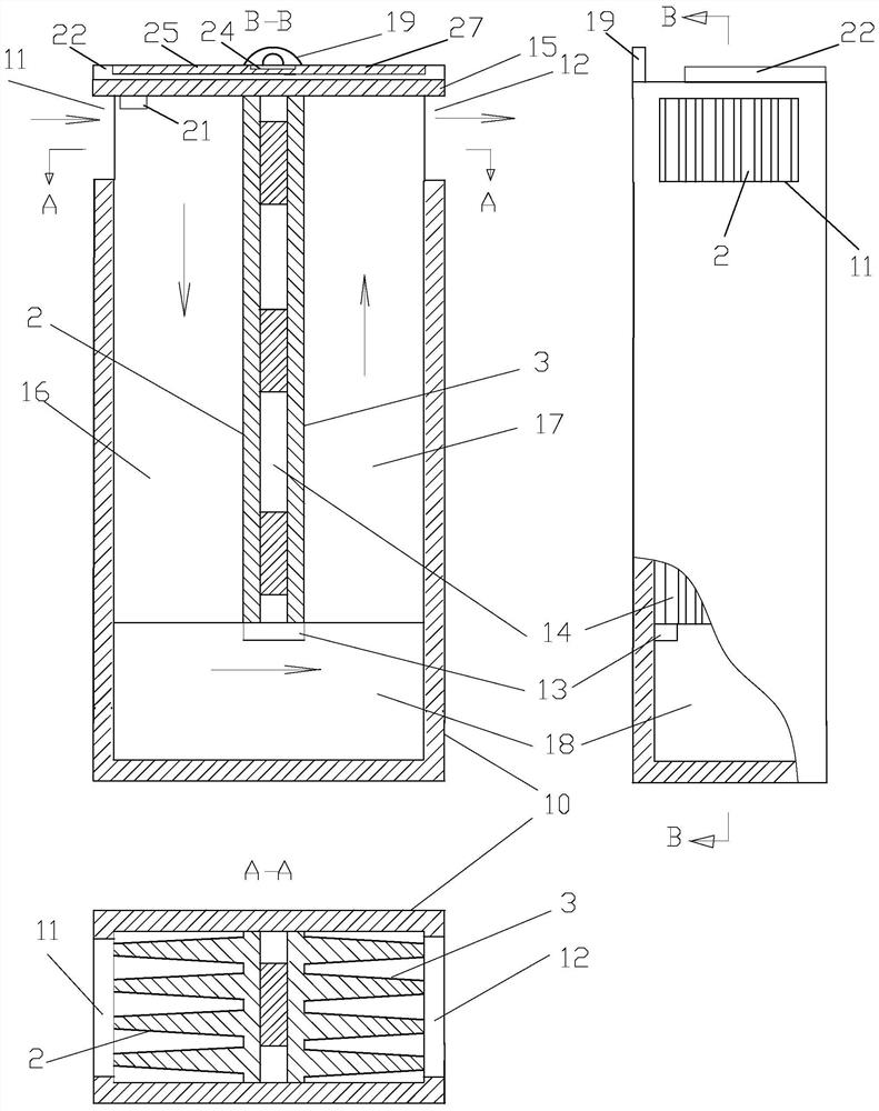
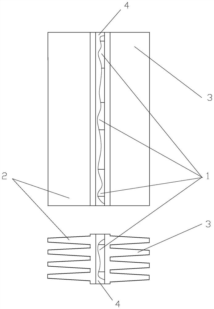
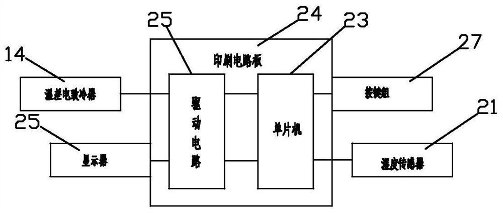
[0018] The dehumidifier in the embodiment of the present invention is improved on the basis of the inventor's previous patent ZL201010104301.0 designed on the basis of a small thermoelectric cooling air dryer, such as figure 1 , figure 2 with image 3 shown. It inherits the design of ZL201010104301.0 including:

[0019] ——The upper part of the left and right sides of the box body 10 with an inner cavity of injection molding has a left opening 11 and a right opening 12 leading to the outside, and the lower 1 / 3~1 / 4 part of the inner cavity of the box body 10 has a shoulder stop 13. Such as figure 2 The shown thermoelectric refrigerator 14 is loaded into the inner cavity of the box body 10 from top to bottom, the lower end reaches the shoulder stop 13, the upper end is tightly pressed by the box cover 15, and the front and rear end surfaces are respectively close to the front and rear walls of the inner cavity. , all the ribs of the cold end radiator 2 are tightly pressed ...


PUM


Abstract

A dehumidifier, including a refrigeration system; characterized in that it also includes: a humidity measuring device, which provides a real-time value of ambient air humidity; a control system, which has a control setting device, and controls the set value and the ambient air humidity according to the humidity The real-time humidity value controls the electric refrigeration system, and has the following working steps: a) the refrigeration system runs until the real-time value of the ambient air humidity is lower than the humidity control set value, or the ambient air humidity is lower than the set value within a specified time. Stop when the real-time value no longer drops; b) When the real-time value of the ambient air humidity exceeds a specified value of the humidity control setting value, repeat step a). The dehumidifier can avoid inefficient or even ineffective energy consumption when the humidity control setting value is relatively low, and the control method and structure are relatively simple, so the reliability is good and the cost is low.

Description

technical field [0001] The invention relates to a dehumidifier, in particular to a control method thereof, and the IPC classification belongs to F24F1 / 02 or F24F11 / 00. Background technique [0002] Traditional dehumidifiers are prone to continuous operation when the humidity control setting is low, resulting in inefficient or even ineffective energy consumption. The relevant improvements made in the prior art for this purpose are relatively complicated and costly, as can be seen in the relevant designs of dehumidifiers retrieved by classification F24F1 / 02 or F24F11 / 00 in the patent database. [0003] Unless otherwise specified in this manual, see the "Mechanical Engineering Handbook" and "Electrical Engineering Handbook" for relevant terms and common knowledge. Contents of the invention [0004] The technical problem to be solved by the present invention is to propose a dehumidifier that can eliminate the inefficient or even ineffective energy consumption described in the...

Claims


Application Information

Patent Timeline
Patent Type & Authority Patents(China)
IPC IPC(8): F24F3/14F24F11/64F24F110/10
CPCF24F3/14F24F2003/144F24F11/64F24F2110/10
Inventor 区长钊
Owner JIANGMEN SUNYA MOTOR CO LTD
Why Eureka
Eureka Blog
Learn More