
A control cable peeling cutter

A technology for controlling cables and blades, which is used in cable installation, cable installation devices, and equipment for dismantling/armored cables, etc. It can solve the problems of cable loop cutting and inconvenient stripping of cable sheaths, and achieve convenient adjustment and convenient removal. The effect of leather work

Active Publication Date: 2019-12-13
茂名市康坦福电力工程有限公司
View PDF6 Cites 0 Cited by
  • Summary
  • Abstract
  • Description
  • Claims
  • Application Information

AI Technical Summary

Problems solved by technology

[0007] The purpose of the present invention is to solve the problem in the prior art that the cables are not ring-cut, and the cable skins after slitting are still inconvenient to peel off, and a control cable peeling cutter is proposed.

Method used

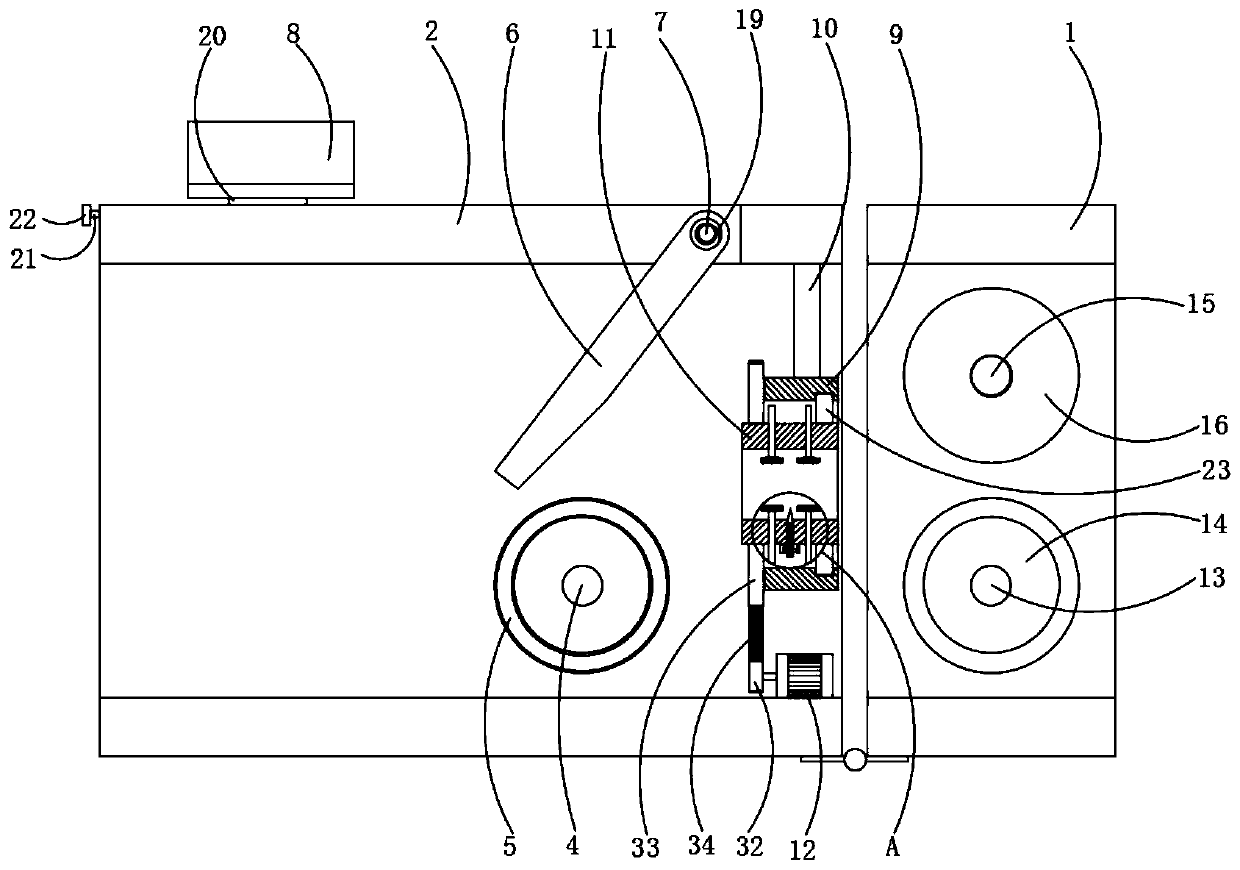
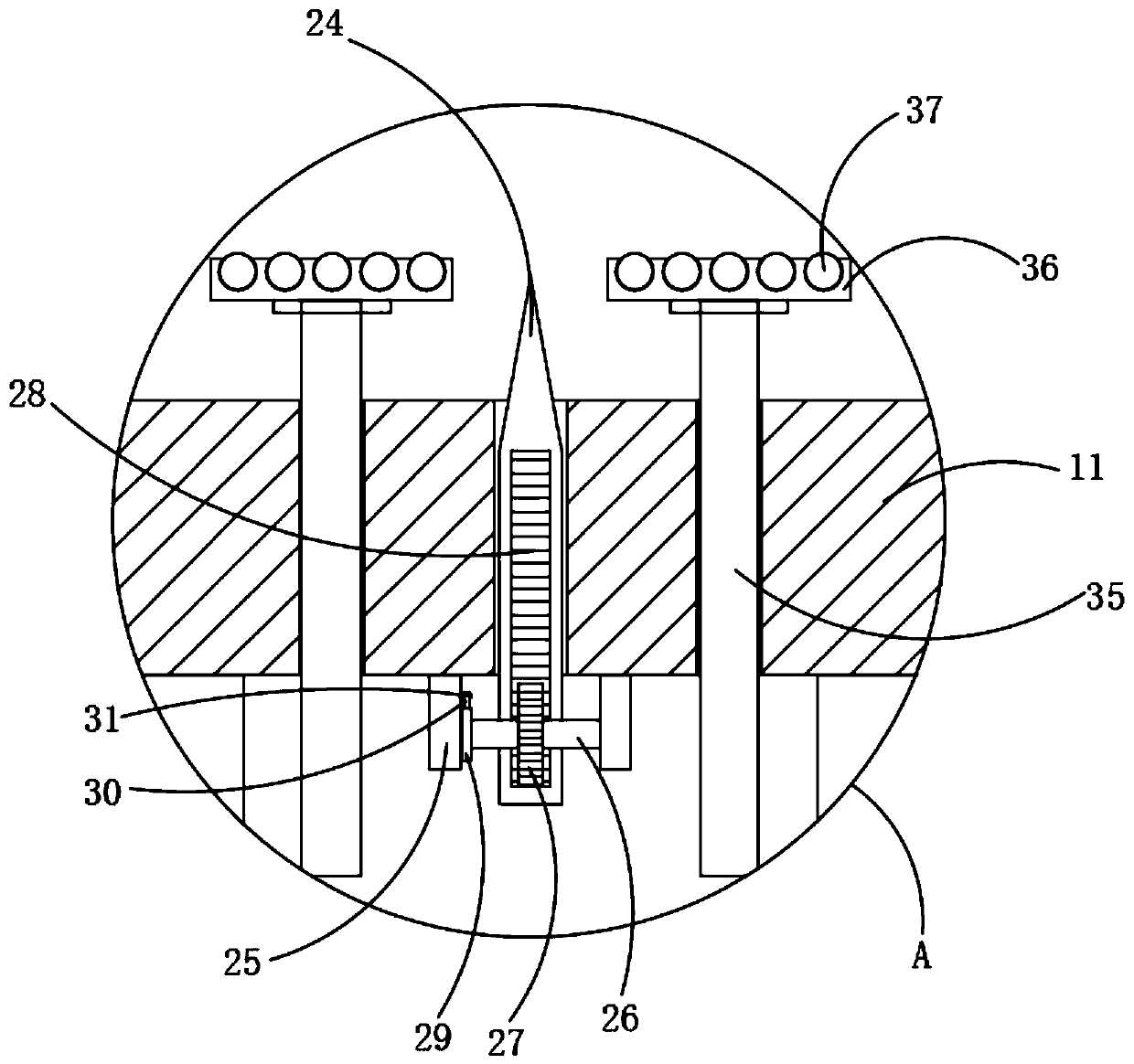
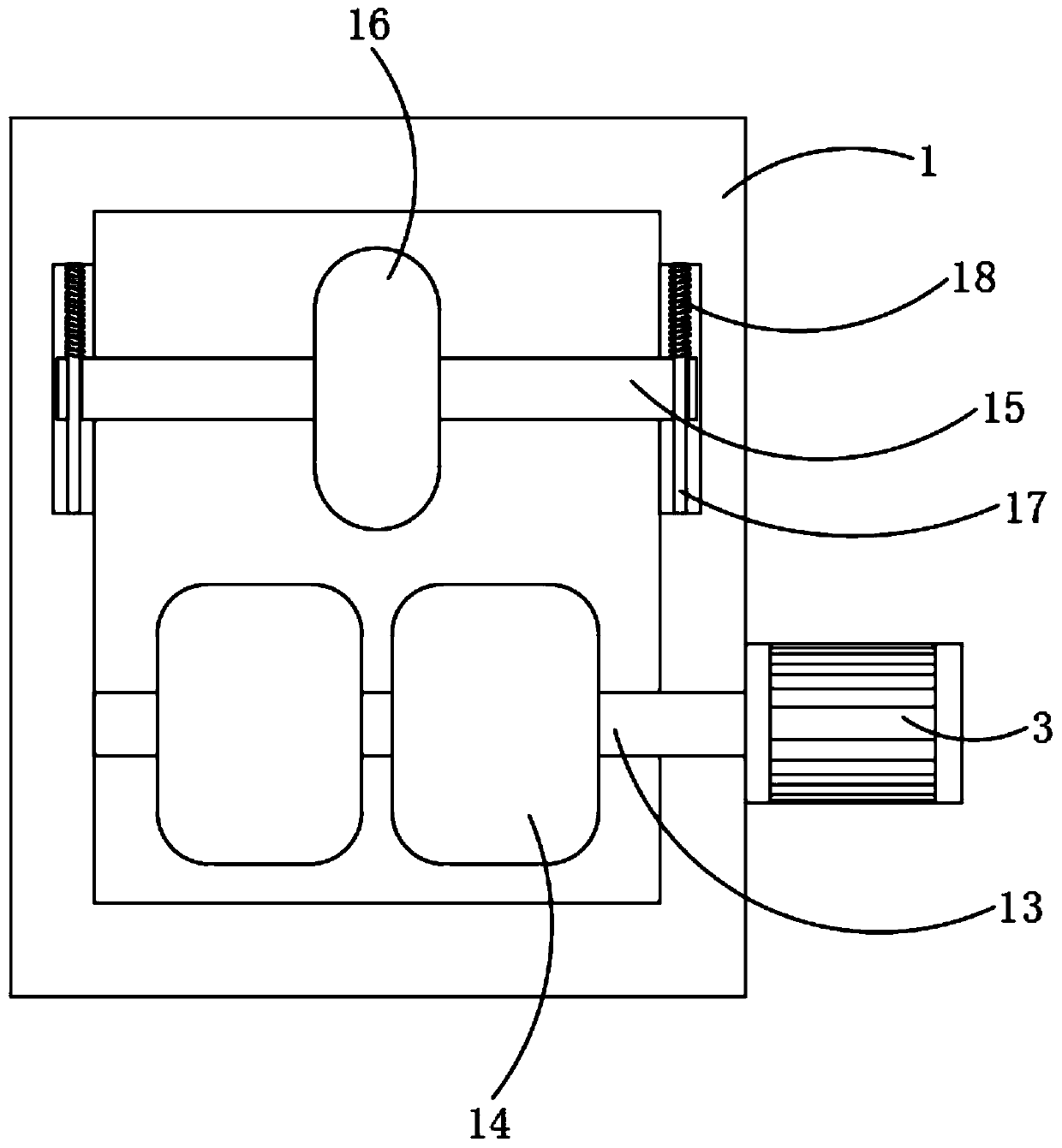

Image

  • A control cable peeling cutter
  • A control cable peeling cutter
  • A control cable peeling cutter

Examples


Embodiment Construction

[0024] The following will clearly and completely describe the technical solutions in the embodiments of the present invention with reference to the accompanying drawings in the embodiments of the present invention. Obviously, the described embodiments are only some, not all, embodiments of the present invention.

[0025] In describing the present invention, it should be understood that the terms "upper", "lower", "front", "rear", "left", "right", "top", "bottom", "inner", " The orientation or positional relationship indicated by "outside", etc. is based on the orientation or positional relationship shown in the drawings, and is only for the convenience of describing the present invention and simplifying the description, rather than indicating or implying that the referred device or element must have a specific orientation, so as to Specific orientation configurations and operations, therefore, are not to be construed as limitations on the invention.

[0026] refer to Figure ...


PUM


Abstract

The invention discloses a peeling cutter of control cables. The peeling cutter of control cables includes a first frame and a second frame which are rotatably connected through a hinge, wherein a material guiding mechanism is arranged in the first frame; a first driving motor is fixed at one side of the first frame; a driving shaft of the first driving motor penetrates the side wall of the first frame and is in drive connection with the material guiding mechanism; the second frame is rotatably connected with a frame roller through a first rotating shaft; the upper side of the frame roller is equipped with a slitting blade; the top of the second frame is provided with a through hole corresponding to the slitting blade; the slitting blade is rotatably connected to the inner side wall of thethrough hole through a second rotating shaft; the upper side of the second frame is in sliding connection with a blade holding rack corresponding to the slitting blade; and a collar is arranged at oneside, adjacent to the first frame, of the frame roller. The peeling cutter of control cables slits a cable while girdling the cable, so as to facilitate the peeling work of the cable, and the depth of girdling is convenient to adjust, so that the peeling cutter of control cables is suitable for cables with different outer skin thicknesses.

Description

technical field [0001] The invention relates to the technical field of electric equipment, in particular to a control cable peeling cutter. Background technique [0002] Control cables are PVC insulated and PVC sheathed control cables suitable for industrial and mining enterprises, energy and transportation departments, and for controlling and protecting lines with AC rated voltage below 450 / 750 volts. [0003] The wire and cable industry is the second largest industry in China after the automobile industry, and the product variety satisfaction rate and domestic market share both exceed 90%. Worldwide, China's wire and cable output has surpassed that of the United States, becoming the world's largest producer of wire and cable. With the rapid development of China's wire and cable industry, the number of new enterprises has been increasing, and the overall technical level of the industry has been greatly improved. [0004] When a substation is newly built or renovated, a la...

Claims


Application Information

Patent Timeline
Patent Type & Authority Patents(China)
IPC IPC(8): H02G1/12
CPCH02G1/1268
Inventor 罗诚
Owner 茂名市康坦福电力工程有限公司
Learn More