Control circuit and switch device

A control circuit and control terminal technology, applied in the field of switches, can solve the problems of low practicability and inability to provide different working voltages and working frequencies for different devices, and achieve the effect of strong practicability

Pending Publication Date: 2018-09-04
CHINA COMM TECH CO LTD +1
View PDF0 Cites 0 Cited by
  • Summary
  • Abstract
  • Description
  • Claims
  • Application Information

AI Technical Summary

Problems solved by technology

[0003] In view of this, the embodiment of the present invention provides a control circuit and a switch device to solve the problem that the switch d

Method used


Image

  • Control circuit and switch device
  • Control circuit and switch device

Examples


Example Embodiment

[0044] Example one

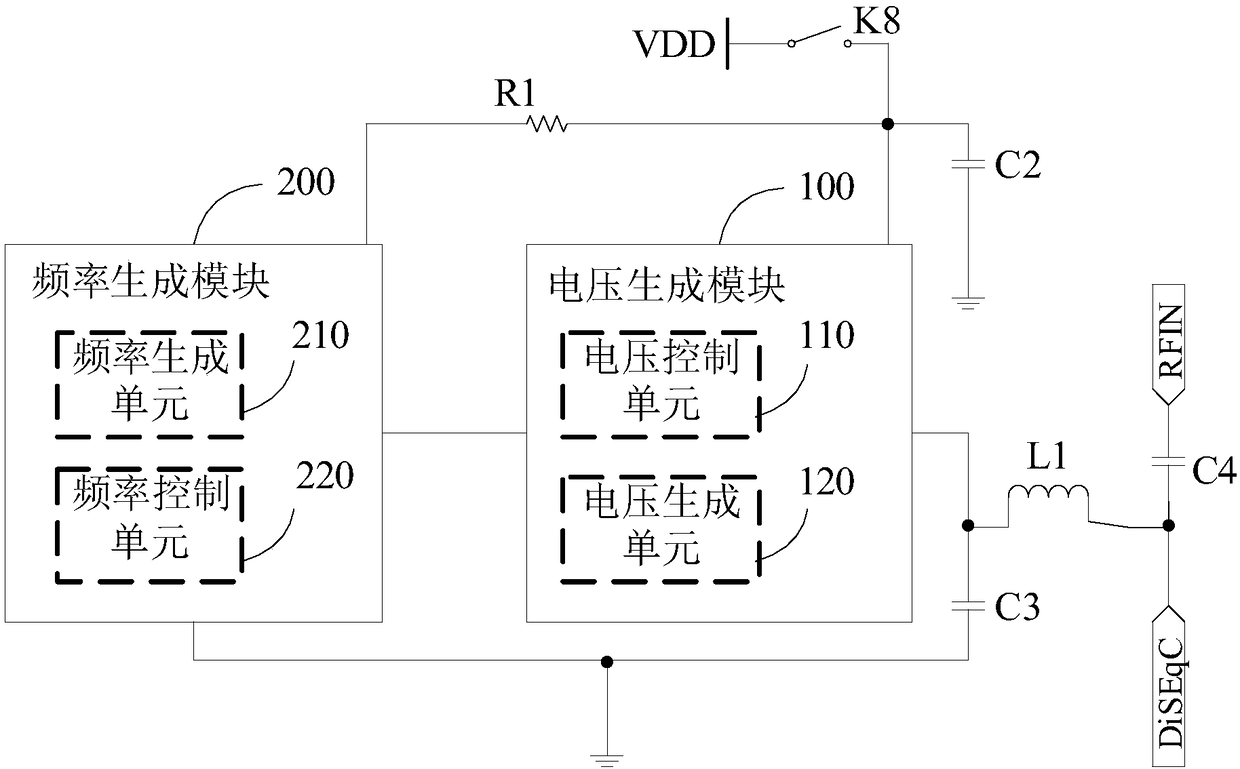
[0045] See figure 1 with figure 2 , A control circuit provided by an embodiment of the present invention includes: a voltage generating module 100 and a frequency generating module 200.

[0046] The voltage generating module 100 is adapted to be connected to an external power supply and an external device, and the voltage generating module 100 is also connected to a frequency generating module 200; the voltage generating module 100 receives the voltage of the external power source and the working signal of the external device, according to the work The signal converts the voltage of the external power supply into at least two voltages, and controls one of the at least two voltages to output to the external device according to user input.

[0047] The voltage generating module 100 also provides a bias voltage for the frequency generating module 200.

[0048] The frequency generating module 200 is adapted to be connected to an external power supply and external eq...

Example Embodiment

[0105] Example two

[0106] This embodiment provides a switch device, which includes a housing and a switch button, and also includes any one of the control circuits as described in the first embodiment, and has the beneficial effects of the above-mentioned control circuit.

[0107] Those skilled in the art can clearly understand that for the convenience and conciseness of the description, only the division of the above-mentioned functional units and modules is used as an example. In practical applications, the above-mentioned functions can be allocated to different functional units and modules as required. Module completion means dividing the internal structure of the device into different functional units or modules to complete all or part of the functions described above. The functional units and modules in the embodiments can be integrated into one processing unit, or each unit can exist alone physically, or two or more units can be integrated into one unit. The above-mentioned...


PUM


Abstract

The invention belongs to the technical field of switches and particularly relates to a control circuit and a switch device. The control circuit comprises a voltage generation module and a frequency generation module, wherein the voltage generation module is connected with an external power supply, external equipment and a frequency generation module and is used for receiving the voltage of the external power supply and a working signal of the external equipment, converting the voltage of the external power supply into at least two voltages according to the working signal and outputting one ofat least two voltages to the external equipment according to user input; the voltage generation module is further used for supplying a bias voltage to the frequency generation module; and the frequency generation module is suitable for being connected with the external power supply, generating a first frequency signal according to the bias voltage and the user input and outputting the first frequency signal as a working frequency to the external equipment according to the user input. According to the control circuit, different voltages and frequencies can be supplied according to different equipment, and the practicability is strong.

Description

technical field [0001] The invention belongs to the technical field of switches, and more specifically relates to a control circuit and a switch device. Background technique [0002] In signal transmission and voltage supply, the switch is used as a control device for turning on or off, and can also be used as a device for providing operating voltage and frequency. For example, in the signal detection process, the signal of the device to be detected needs to enter the signal detection device through the switch device. At this time, the switch device provides the operating voltage and frequency for the device to be detected. However, the switch device in the prior art is only for One type of equipment to be tested provides one voltage and frequency. When multiple types of equipment to be tested require signal detection, multiple switching devices need to be added to provide voltage and frequency, which is very low in practicability. Contents of the invention [0003] In vi...

Claims


Application Information

Patent Timeline
IPC IPC(8): H02M1/08
CPCH02M1/08
Inventor 何宏平项俊晖刘俊杰沈佳鹏潘雄广
Owner CHINA COMM TECH CO LTD
Why Eureka
Try Eureka