Deicing system for road surface

A ground and road technology, applied in the direction of roads, roads, pavement details, etc., can solve the problems of low deicing efficiency, affecting travel and safety, and extreme weather cannot determine the region and time, so as to reduce the traffic accident rate and ice melting efficiency High, the effect of saving the overall cost of society

Inactive Publication Date: 2018-09-07
CHINA FIRST METALLURGICAL GROUP
View PDF5 Cites 2 Cited by
  • Summary
  • Abstract
  • Description
  • Claims
  • Application Information

AI Technical Summary

Problems solved by technology

[0002] At present, natural disasters in ice and snow weather often occur, and the region and time cannot be determined due to extreme weather, which seriously affects people's travel and safety. These methods are traditional and have low deicing efficiency

Method used


Image

  • Deicing system for road surface
  • Deicing system for road surface

Examples


Embodiment Construction

[0022] It should be understood that the specific embodiments described here are only used to explain the present invention, not to limit the present invention.

[0023] It should be noted that, in the description of the present invention, the terms "horizontal", "vertical", "upper", "lower", "front", "rear", "left", "right", "vertical", The orientation or positional relationship indicated by "horizontal", "top", "bottom", "inner", "outer", etc. is based on the orientation or positional relationship shown in the drawings, and is only for the convenience of describing the present invention and simplifying the description, and It is not to indicate or imply that the device or element referred to must have a particular orientation, be constructed in a particular orientation, or operate in a particular orientation, and thus should not be construed as limiting the invention.

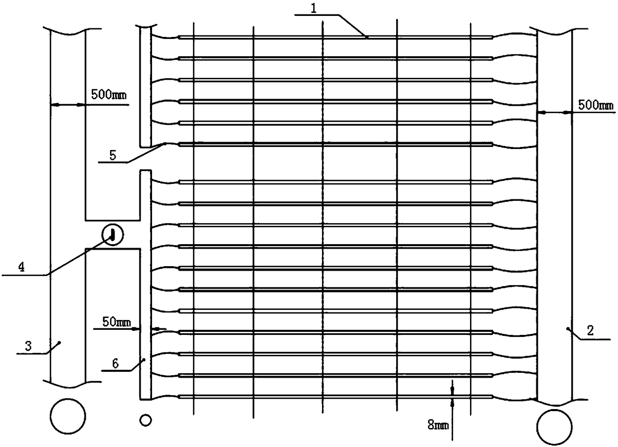
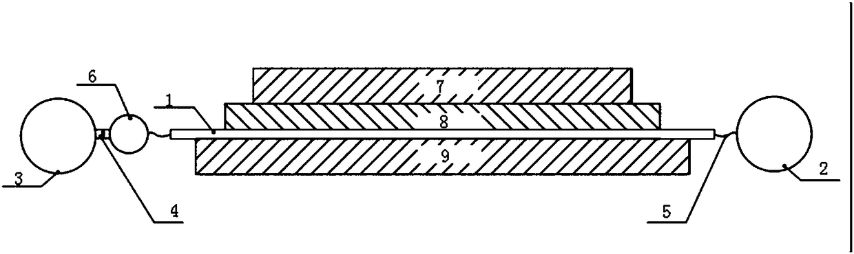
[0024] refer to figure 1 and figure 2 , in this preferred embodiment, a deicing system for road surfaces...


PUM


Abstract

The invention discloses a deicing system for a road surface. The deicing system comprises a plurality of thermodynamic pipes which are pre-buried in a ground road, an inlet pipe communicated with inlet ends of all the thermodynamic pipes, a water outlet pipe communicated with outlet ends of all the thermodynamic pipes and a heat supply source communicated with the inlet pipe; a temperature controlswitch is further mounted between the water outlet pipe and the thermodynamic pipes. According to the deicing system for the road surface, provided by the invention, the road deicing efficiency is improved.

Description

technical field [0001] The invention relates to the technical field of ice melting, in particular to an ice melting system for road surfaces. Background technique [0002] At present, natural disasters in ice and snow weather often occur, and the region and time cannot be determined due to extreme weather, which seriously affects people's travel and safety. These methods are traditional and have low deicing efficiency. Contents of the invention [0003] The main purpose of the present invention is to provide a deicing system for road surface, aiming at improving the deicing efficiency of the road. [0004] In order to achieve the above purpose, the present invention provides a road deicing system, which includes a plurality of heat pipes pre-buried in the ground road, an inlet pipe connected to the inlet ends of all heat pipes, and a pipe connected to the outlet ends of all heat pipes. The water outlet pipe and the heat supply source communicated with the inlet pipe, whe...

Claims


Application Information

Patent Timeline
Patent Type & Authority Applications(China)
IPC IPC(8): E01C11/26
CPCE01C11/26
Inventor 郑金平王朋林文剑肖祥
Owner CHINA FIRST METALLURGICAL GROUP
Why Eureka
Try Eureka