A Pressure regulation servo-valve with reduced leakage flow rate

A technology of pressure regulation and servo valve, which is applied in the direction of fluid pressure control, fluid pressure actuation device, servo motor assembly, etc., and can solve problems such as difficulty in starting

Active Publication Date: 2018-09-07
SAFRAN LANDING SYSTEMS
View PDF8 Cites 0 Cited by
  • Summary
  • Abstract
  • Description
  • Claims
  • Application Information

AI Technical Summary

Problems solved by technology

Difficulty starting is then observed and may sometimes be accompanied by fluctuations in utilization pressure

Method used


Image

  • A Pressure regulation servo-valve with reduced leakage flow rate

Examples


Embodiment Construction

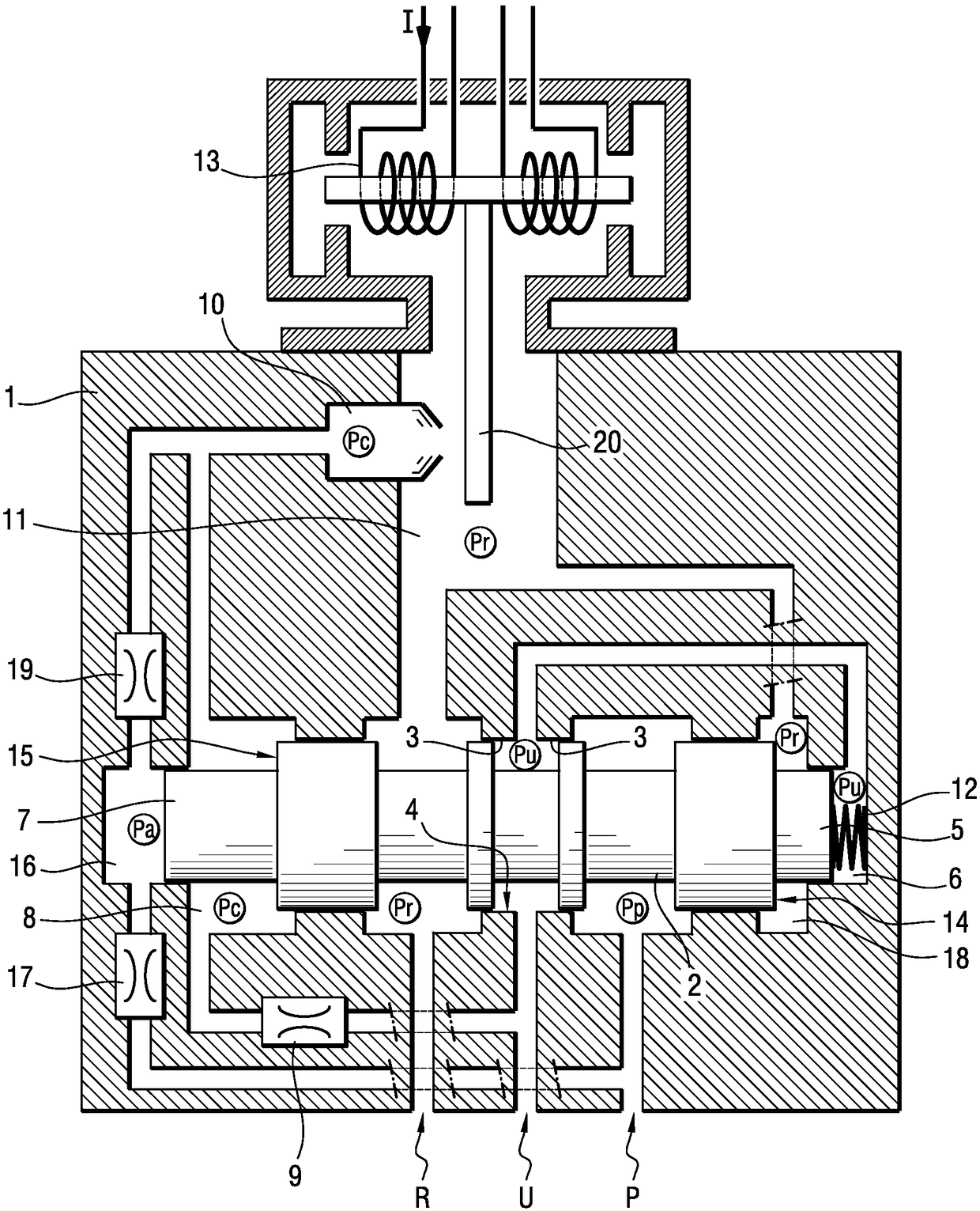
[0012] Referring to the drawings, the pressure regulator servo valve of the present invention comprises: a main body or cylinder 1 having a feed port P for connection to a source of hydraulic fluid under pressure; a return port R for connection to a to a tank (not shown); and with port U for connection to a piece of equipment, such as a hydraulic chamber (not shown) of an aircraft brake.

[0013] The spool 2 is slidably mounted in a calibrated orifice in the body 1 . The spool 2 has a land 3 cooperating with a central portion 4 of the calibrated orifice with slight clearance and extending firstly between the utilization port U and the return port R, and secondly between the utilization port U and the feed port P.

[0014] Due to the sliding gap between the table 3 and the central portion 4 of the calibration orifice, a channel providing communication between the utilization port U and both the return port R and the feed port P remains. In the position shown, the passage betwe...


PUM


Abstract

The invention relates to a pressure regulation servo-valve comprising a body having a utilization port, a feed port, and a return port, a spool mounted as a sliding fit in the body, the spool co-operating with the body to define a pilot chamber connected to the utilization port. The spool and the body together further define a priming chamber connected to the feed port via a second constriction and connected to the nozzle via a third constriction, and in which there exists a priming pressure acting on the spool in the first direction.

Description

technical field [0001] The present invention relates to a pressure regulating servo valve with reduced leakage flow. Background technique [0002] Servo valves of this type are used, for example, to control hydraulic brakes of vehicles, in particular aircraft brakes. [0003] A known pressure regulating servo valve includes a body having a utilization port, a supply port, and a return port, and a spool movably mounted in the body to communicate the utilization port with the supply port or with the return port. An end of the spool cooperates with the body to define at least one pilot chamber connected to a nozzle arranged to open into a cavity connected to the return port. A baffle extending in the cavity and facing the nozzle is mounted to move in a controlled manner. The pilot chamber is connected to the supply port via the constriction. Where applicable, the servo valve may have two pilot chambers exerting opposing forces on the spool, each pilot chamber being connected...

Claims


Application Information

Patent Timeline
Patent Type & Authority Applications(China)
IPC IPC(8): F16K11/065F16K31/363
CPCF16K11/065F16K31/363G05D16/166G05D16/2097G05D16/2024F15B13/0402F15B13/0438Y10T137/8659B64C25/44F15B13/021F15B13/0444F15B5/003B64C25/42F15B5/00
Inventor A·布莱恩科 马乔勒特D·德隆
Owner SAFRAN LANDING SYSTEMS
Why Eureka
Try Eureka