Manufacturing method of printed antenna assembly, printed antenna assembly and electronic equipment

A technology of printing antennas and manufacturing methods, which is applied in the electronic field, can solve the problems of limited space for electronic equipment, increase the size of electronic equipment, etc., and achieve the effect of improving the radiation signal strength and increasing the headroom area

Inactive Publication Date: 2018-09-07
GUANGDONG OPPO MOBILE TELECOMM CORP LTD
View PDF4 Cites 0 Cited by
  • Summary
  • Abstract
  • Description
  • Claims
  • Application Information

AI Technical Summary

Problems solved by technology

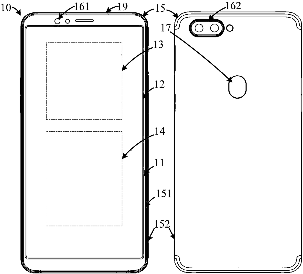
[0003] However, as the functions of electronic equipment become more and more, the space of electronic equipment becomes more and more limited. Increasing the clearance area of ​​the antenna structure inside the electronic equipment will occupy the space of other devices. If the size of the electronic equipment is not changed, the electronic equipment will be affected. functions, increases the size of the electronic device without affecting the function of the electronic device

Method used


Image

  • Manufacturing method of printed antenna assembly, printed antenna assembly and electronic equipment
  • Manufacturing method of printed antenna assembly, printed antenna assembly and electronic equipment
  • Manufacturing method of printed antenna assembly, printed antenna assembly and electronic equipment

Examples


Embodiment Construction

[0030] The technical solutions in the embodiments of the present application will be clearly and completely described below in conjunction with the drawings in the embodiments of the present application. Apparently, the described embodiments are only some of the embodiments of this application, not all of them. Based on the embodiments in this application, all other embodiments obtained by those skilled in the art without making creative efforts belong to the scope of protection of this application.

[0031] In the description of the present application, it should be understood that the terms "center", "longitudinal", "transverse", "length", "width", "thickness", "upper", "lower", "front", " Orientation indicated by rear, left, right, vertical, horizontal, top, bottom, inside, outside, clockwise, counterclockwise, etc. The positional relationship is based on the orientation or positional relationship shown in the drawings, which is only for the convenience of describing the a...


PUM


Abstract

The embodiment of the invention provides a manufacturing method of a printed antenna assembly, the printed antenna assembly and electronic equipment. The manufacturing method of the antenna assembly comprises the following steps: providing a substrate, wherein the outer surface of the substrate is provided with a printing area; carrying out first printing treatment on the printing area to form a first printed antenna; carrying out second printing treatment on the printing area to form a second printed antenna, wherein the first printed antenna is covered with the position of the joint of the second printed antenna and the first printed circuit to form a boss; carrying out oil paint spraying treatment on the substrate after second printing treatment to form an oil paint layer, wherein the first printed antenna, the second printed antenna and the outer surface of the substrate are covered with the oil paint layer, forming a first inclined surface of the oil paint layer from the boss to the edge of the first printed antenna, and forming a smooth second inclined surface from the boss to the periphery of the second printed antenna. Through the embodiment, the clearance area of the electronic equipment can be increased, and the radiation signal intensity of the electronic equipment is promoted.

Description

technical field [0001] The present application relates to the field of electronic technology, in particular to a method for manufacturing a printed antenna assembly, a printed antenna assembly and electronic equipment. Background technique [0002] With the development of communication technology, electronic devices such as smartphones are becoming more and more popular. During the use of electronic equipment, such as using electronic equipment to talk. In order to improve the call quality, the clearance area of ​​the antenna structure can be increased inside the electronic device. [0003] However, with more and more functions of electronic equipment, the space of electronic equipment is becoming more and more limited. Increasing the clearance area of ​​the antenna structure inside the electronic equipment will occupy the space of other devices. If the size of the electronic equipment is not changed, the electronic equipment will be affected. The function of the electroni...

Claims


Application Information

Patent Timeline
Patent Type & Authority Applications(China)
IPC IPC(8): H01Q1/38H01Q1/40H01Q1/22H01Q1/24
CPCH01Q1/2258H01Q1/242H01Q1/38H01Q1/40
Inventor 杨光明
Owner GUANGDONG OPPO MOBILE TELECOMM CORP LTD
Why Eureka
Try Eureka