
Power electronic equipment storage equipment

A technology for power electronics and equipment, which is applied to the field of power electronic equipment storage equipment, can solve problems such as unfavorable use, inconvenient partition adjustment, inconvenient partition distance adjustment, etc., and achieves the effects of convenient operation, high practical performance and simple structure

Inactive Publication Date: 2018-09-11
YANTAI POWER SUPPLY COMPANY OF STATE GRID SHANDONG ELECTRIC POWER +1
View PDF6 Cites 8 Cited by
  • Summary
  • Abstract
  • Description
  • Claims
  • Application Information

AI Technical Summary

Problems solved by technology

[0003] But above-mentioned this kind of design still has shortcomings, and above-mentioned this kind of design is inconvenient to adjust the position of the partition, thus it is not convenient to adjust the distance between the adjacent two partitions, so that the distance between the adjacent partitions The height of the room cannot match the height of the electronic equipment well, and the space in the storage box cannot be used reasonably, which is not conducive to people's use. Therefore, we propose a storage device for power electronic equipment to solve the above problems

Method used


Image

  • Power electronic equipment storage equipment
  • Power electronic equipment storage equipment
  • Power electronic equipment storage equipment

Examples


Embodiment

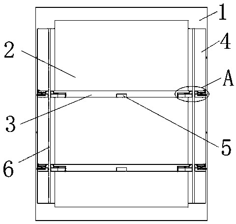
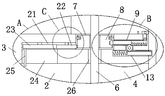
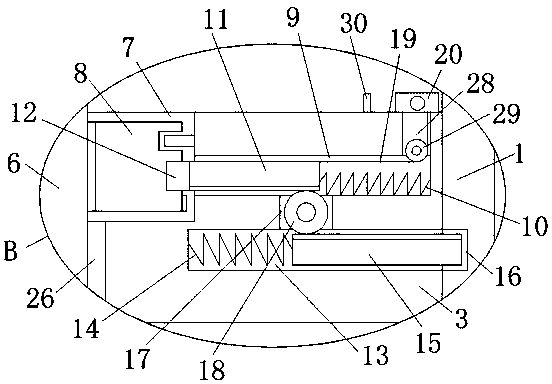
[0027] refer to Figure 1-5In this embodiment, a storage device for power electronic equipment is proposed, which includes a storage box 1, a storage cavity 2 is provided on the storage box 1, adjustment grooves 4 are opened on the inner walls of both sides of the storage cavity 2, and the storage cavity 2 is provided with There are a plurality of partitions 3, the two sides of the partitions 3 respectively extend into the two adjustment grooves 4, the two sides of the partitions 3 are slidingly connected with the inner wall of the side of the two adjustment grooves 4 which are far away from each other, and the bottom of the partitions 3 A positioning groove 5 is provided, the same screw rod 6 is welded on the top inner wall and the bottom inner wall of the adjusting groove 4, two symmetrically arranged rotating grooves 7 are opened on the top of the partition plate 3, and multiple screw rods 6 are installed on the outer thread Turntable 8, a plurality of turntables 8 and a pl...


PUM


Abstract

The invention discloses power electronic equipment storage equipment which comprises a storage box. A storage cavity is arranged on the storage box, adjusting grooves are formed in the inner walls ofthe two sides of the storage cavity, a plurality of separating plates are arranged in the storage cavity, the two sides of each separating plate extend into the two adjusting grooves, the two sides ofeach separating plate are in sliding connection with the inner walls of the sides, far away from each other, of the two adjusting grooves, positioning grooves are formed in the bottoms of the separating plates, one lead screw is welded to the inner walls of the top and the bottom of each adjusting groove, two symmetrically-arranged rotating grooves are formed in the top of each separating plate,a plurality of rotating discs are installed on the outer side of each lead screw in a threaded manner, and the multiple rotating discs and the multiple rotating grooves are arranged in a one-to-one correspondence manner. The power electronic equipment storage equipment is high in practical performance, simple in structure and convenient to operate, the distance between every two adjacent separating plates can be adjusted, electronic equipment with different heights can be stored in the storage box, the space in the storage box is reasonably used, and use by people is facilitated.

Description

technical field [0001] The invention relates to the technical field of power equipment accessories, in particular to a storage device for power electronic equipment. Background technique [0002] Commonly used electronic equipment in the field of electric power, such as electronic switches, converters, electronic AC power controllers, etc., play a key role in maintaining and controlling the normal operation of electric power. Therefore, in order to prolong the service life of electronic switches, etc., for emergency use , most of these electronic devices will be stored in the storage box of electronic equipment by people. After retrieval, the patent document with the application publication number of CN106628523A provides a storage device for power electronic equipment. This design includes a box body, and the lower end of the box body is equipped with The base, the box body includes the box door, and the inner side of the box body is provided with U-shaped grooves that are ...

Claims


Application Information

Patent Timeline
IPC IPC(8): B65D25/06
CPCB65D25/06
Inventor 刘扬张一荻张文韬张照梅范丽安好好李强杜兴远刘卫东尹潇刘振华袁媛李茜宇孙超仲海崔腾刘华林宋雅然
Owner YANTAI POWER SUPPLY COMPANY OF STATE GRID SHANDONG ELECTRIC POWER
Learn More