An environmental protection precipitation device

A precipitation device, an environmentally friendly technology, applied in the fields of flocculation/sedimentation water/sewage treatment, chemical instruments and methods, water/sludge/sewage treatment, etc. problem, to achieve the effect of significant purification effect, easy operation and improved efficiency

Active Publication Date: 2019-05-10
佛山市汇之源金本污水处理有限公司
View PDF5 Cites 0 Cited by
  • Summary
  • Abstract
  • Description
  • Claims
  • Application Information

AI Technical Summary

Problems solved by technology

[0003] Traditional sewage treatment facilities use grids to carry out residual filtration of floating fixed waste in sewage. More garbage is easy to block the grid, requiring manual cleaning, which is time-consuming and laborious, and affects the efficiency of sewage treatment.

Method used


Image

  • An environmental protection precipitation device
  • An environmental protection precipitation device
  • An environmental protection precipitation device

Examples


Embodiment 1

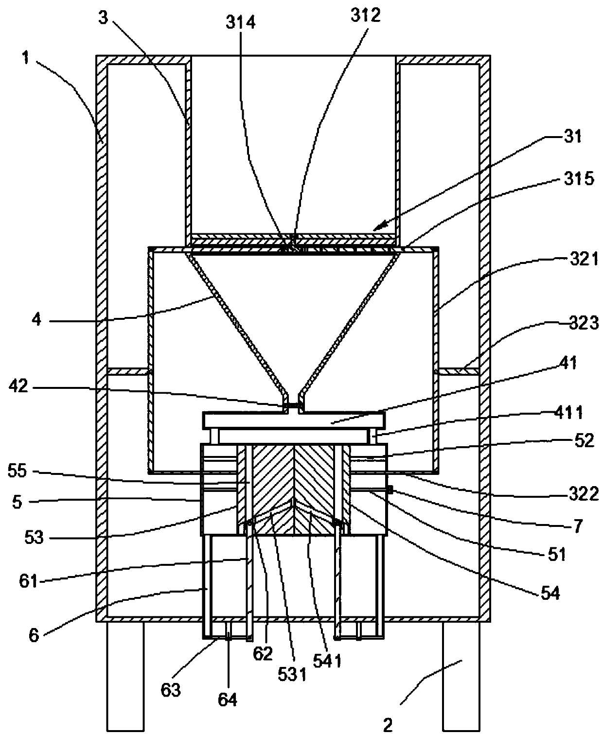
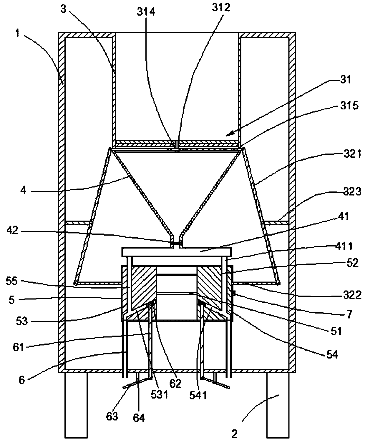
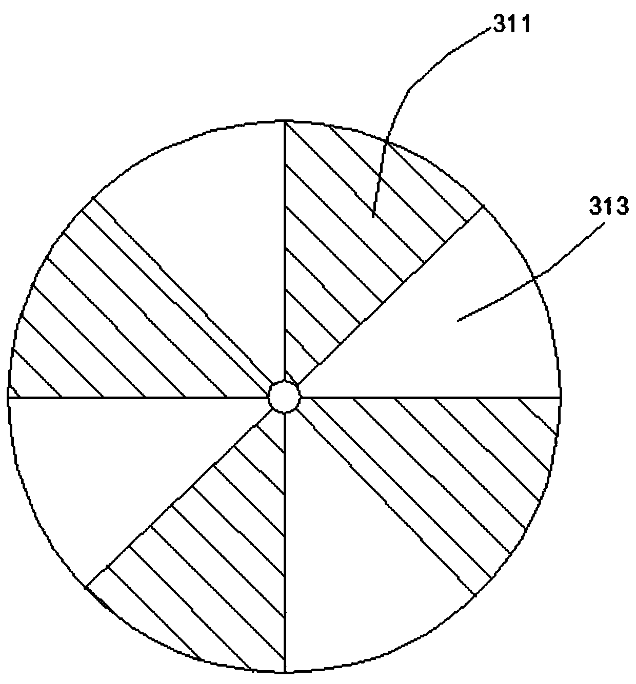
[0023] Such as Figure 1-5 As shown, the present embodiment provides an environment-friendly sedimentation device, including a frame 1 and support legs 2 at the bottom thereof. The inside of the frame 1 is provided with a water storage chamber 3, a conical sedimentation tank 4, a sliding Cavity 5 and precipitation outlet pipe 6, the bottom of the water storage chamber 3 and the top of the conical sedimentation tank 4 are isolated by a movable isolation plate 31, and the movable isolation plate 31 includes coaxial fixed blades 311 and movable blades 313. The bottom of the conical sedimentation tank 4 is connected to the slide chamber 5 through the guide pipes 411 at both ends of the guide chamber 41, and the slide chamber 5 is provided with a screw rod extending left and right through the left slide block 53 and the right slide block 54 51 and slide bar 52, and screw rod 51 is connected with left slide block 53 and right slide block 54 respectively by the screw thread of direct...

Embodiment 2

[0025] Such as Figure 1-5 As shown, the present embodiment provides an environment-friendly sedimentation device, including a frame 1 and support legs 2 at the bottom thereof. The inside of the frame 1 is provided with a water storage chamber 3, a conical sedimentation tank 4, a sliding Cavity 5 and precipitation outlet pipe 6, the bottom of the water storage chamber 3 and the top of the conical sedimentation tank 4 are isolated by a movable isolation plate 31, and the movable isolation plate 31 includes coaxial fixed blades 311 and movable blades 313. The bottom of the conical sedimentation tank 4 is connected to the slide chamber 5 through the guide pipes 411 at both ends of the guide chamber 41, and the slide chamber 5 is provided with a screw rod extending left and right through the left slide block 53 and the right slide block 54 51 and slide bar 52, and screw rod 51 is connected with left slide block 53 and right slide block 54 respectively by the screw thread of direct...

Embodiment 3

[0027] Such as Figure 1-5 As shown, the present embodiment provides an environment-friendly sedimentation device, including a frame 1 and support legs 2 at the bottom thereof. The inside of the frame 1 is provided with a water storage chamber 3, a conical sedimentation tank 4, a sliding Cavity 5 and precipitation outlet pipe 6, the bottom of the water storage chamber 3 and the top of the conical sedimentation tank 4 are isolated by a movable isolation plate 31, and the movable isolation plate 31 includes coaxial fixed blades 311 and movable blades 313. The bottom of the conical sedimentation tank 4 is connected to the slide chamber 5 through the guide pipes 411 at both ends of the guide chamber 41, and the slide chamber 5 is provided with a screw rod extending left and right through the left slide block 53 and the right slide block 54 51 and slide bar 52, and screw rod 51 is connected with left slide block 53 and right slide block 54 respectively by the screw thread of direct...


PUM


Abstract

The invention provides an environment-friendly sedimentation device. The device comprises a rack and supporting legs on the bottom of the rack, wherein the rack is internally provided with a water storage cavity, a cone-shaped sedimentation pond, a sliding cavity and sediment outlet pipelines from top to bottom, the bottom of the water storage cavity and the top of the cone-shaped sedimentation pond are isolated by a movable isolation board, the movable isolation board comprises coaxial fixed blades and movable blades, the bottom of the cone-shaped sedimentation pond is communicated with the sliding cavity through guiding pipes at the two ends of a guiding cavity, the sliding cavity is internally provided with a screw and a sliding rod which penetrate a left sliding block and a right sliding block and extend in the left and right directions, the screw is connected with the left sliding block and the right sliding block through threads in opposite directions, one end of the screw is indriving connection with a motor, and both the left sliding block and the right sliding block are internally provided with a communicating cavity which is connected and communicated with the corresponding guiding pipe and the corresponding sediment outlet pipeline. Opening of the environment-friendly sedimentation device and sediment separation work are automatically controlled, and thus the sediment treatment efficiency is improved.

Description

technical field [0001] The invention relates to an environment-friendly precipitation device. Background technique [0002] Sewage treatment (wastewater treatment): The process of purifying sewage to meet the water quality requirements of a certain water body for drainage or reuse. Sewage treatment is widely used in various fields such as construction, agriculture, transportation, energy, petrochemical, environmental protection, urban landscape, medical treatment, catering, etc., and it is also increasingly entering the daily life of ordinary people. [0003] Traditional sewage treatment facilities use grids to carry out residual filtration of floating fixed waste in sewage. More garbage is easy to block the grid, requiring manual cleaning, which is time-consuming and laborious, and affects the efficiency of sewage treatment. Contents of the invention [0004] The object of the present invention is to provide an environmental protection sedimentation device, comprising a ...

Claims


Application Information

Patent Timeline
Patent Type & Authority Patents(China)
IPC IPC(8): C02F1/52
CPCC02F1/5281
Inventor 徐坤
Owner 佛山市汇之源金本污水处理有限公司
Why Eureka
Try Eureka