A combined bridge truss with fastening mechanism

A fastening mechanism and combined technology, applied in the direction of bridges, truss bridges, bridge forms, etc., can solve the problems of unfavorable bridge truss rapid installation, etc., and achieve the effect of convenient viewing and modification

Active Publication Date: 2020-10-30
泉州市惠安县铸铭贸易有限公司
View PDF6 Cites 0 Cited by
  • Summary
  • Abstract
  • Description
  • Claims
  • Application Information

AI Technical Summary

Problems solved by technology

[0004] The object of the present invention is to provide a combined bridge truss with a fastening mechanism to solve the above-mentioned background technology. Although there are certain fixed installation and connection combinations inside the bridge truss in the market, usually only one layer of clips is used inside. Lock them together, and then fix them with bolts. This connection method is not conducive to the rapid installation of the basic display of bridge trusses.

Method used


Image

  • A combined bridge truss with fastening mechanism
  • A combined bridge truss with fastening mechanism
  • A combined bridge truss with fastening mechanism

Examples


Embodiment Construction

[0017] The technical solutions in the embodiments of the present invention will be clearly and completely described below with reference to the accompanying drawings in the embodiments of the present invention. Obviously, the described embodiments are only a part of the embodiments of the present invention, but not all of the embodiments. Based on the embodiments of the present invention, all other embodiments obtained by those of ordinary skill in the art without creative efforts shall fall within the protection scope of the present invention.

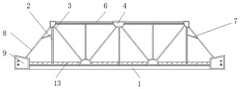
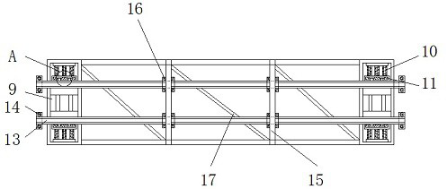
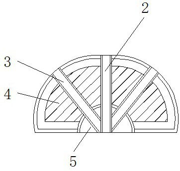
[0018] see Figure 1-4 , the present invention provides a technical solution: a combined bridge truss with a fastening mechanism, including a lower flat longitudinal connecting frame 1, a longitudinal frame 2, an oblique vertical connecting frame 3, a connecting block 4, a friction connecting block 5, and a top truss 6 , support bar 7, bridge gantry 8, vertical fixing block 9, spring 10, limit table 11, limit block 12, connecting plat...


PUM


Abstract

The invention discloses a combined bridge truss with a fastening mechanism. The truss comprises a lower flat longitudinal connecting frame, a top truss and a spring, the upper end of the lower flat longitudinal connecting frame is connected with a vertical frame, one end of the vertical frame is fixed to a diagonal longitudinal connecting frame, connecting blocks are arranged on the upper and lower ends of the diagonal longitudinal connecting frame, friction connecting blocks are fixed inside the connecting blocks, the top truss is connected to the upper end of the vertical frame, the left andright sides of the vertical frame are fixedly to support strips, bridge door frames are connected to the outer sides of the support strips, and connecting longitudinal fixing blocks are mounted on the sides of the bridge door frames. According to the combined bridge truss with the fastening mechanism, the vertical frame and the diagonal longitudinal connecting frame form a disassembling structurethrough the connecting blocks, the vertical frame and the diagonal longitudinal connecting frame can be combined and opposed, the joint of the vertical frame and the diagonal longitudinal connectingframe is slidably clamped with the insides of the connecting blocks, so that the connecting blocks between the vertical frame and the diagonal longitudinal connecting frame are and connected and fixed, and the friction connecting blocks inside the connecting blocks perform secondary friction fixing on the joint between the vertical frame and the diagonal longitudinal connecting frame.

Description

technical field [0001] The invention relates to the technical field of bridge trusses, in particular to a combined bridge truss with a fastening mechanism. Background technique [0002] A truss bridge refers to a bridge with a truss as the main load-bearing member of the upper structure. A truss bridge is generally composed of a main bridge, an upper and lower horizontal longitudinal connection, a bridge gantry, an intermediate transverse brace and a bridge deck system. In the truss, the chord is the The members that make up the periphery of the truss include the upper chord and the lower chord. The members connecting the upper and lower chords are called web members, which are divided into oblique rods and vertical rods according to the direction of the web members. The plane where the chord rod and the web rod are located is It is called the main truss plane. The bridge height of the long-span bridge changes along the span direction to form a curved chord truss; the medium...

Claims


Application Information

Patent Timeline
Patent Type & Authority Patents(China)
IPC IPC(8): E01D6/00
CPCE01D6/00
Inventor 黄宇松
Owner 泉州市惠安县铸铭贸易有限公司
Why Eureka
Try Eureka