Design method of four-component zoom telecentric optical system

A technology of telecentric optical system and design method, applied in optics, optical components, instruments, etc., can solve problems such as inability to realize focal plane position control

Inactive Publication Date: 2018-09-14
SHANGHAI INST OF OPTICS & FINE MECHANICS CHINESE ACAD OF SCI
View PDF2 Cites 2 Cited by
  • Summary
  • Abstract
  • Description
  • Claims
  • Application Information

AI Technical Summary

Problems solved by technology

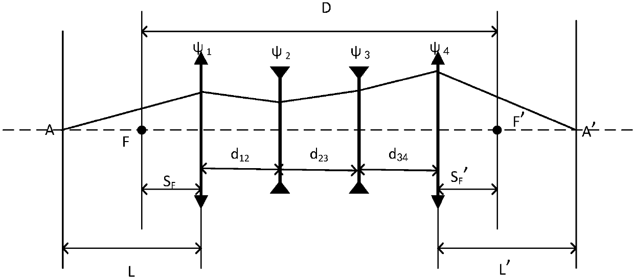
[0004] The invention provides a design method for a four-component zoom telecentric optical system. The method aims at finite distance imaging and uses a Gau

Method used


Image

  • Design method of four-component zoom telecentric optical system
  • Design method of four-component zoom telecentric optical system
  • Design method of four-component zoom telecentric optical system

Examples


Embodiment Construction

[0016] The technical solutions of the present invention will be further described in detail below in conjunction with the accompanying drawings and embodiments, but the protection scope of the present invention should not be limited thereto.

[0017] Design principle of the present invention is as follows:

[0018] Step 1: Determine the overall structure of the four-element zoom telecentric system according to the requirements of use

[0019] There are usually three structures to realize the zoom telecentric system: (1) A movable aperture diaphragm is placed inside the zoom system, and the aperture diaphragm moves with the movement of the lens group when zooming. (2) More lens groups are introduced to simultaneously control the positions of the image plane and the focal plane. (3) Make the entrance pupil in front of the system. What the present invention has used is the third kind of structure, promptly adopts the form of four components, and the optical power of lens group ...


PUM


Abstract

The invention discloses a design method of a four-component zoom telecentric optical system and relates to the technical field of optical design. The design method comprises the steps as follows: (1)determining the structure form of the four-component zoom telecentric system; (2) supposing the distance between the front focal plane of the system and the first surface of the system is SF, the distance between the back focal plane and the last surface of the system is SF', the distance between a first component and a second component is d12, the distance between the second component and a thirdcomponent is d23 and the distance between the third component and a fourth component is d34; (3) making the distance D between the front and back focuses of the four-component zoom telecentric systemsatisfy the following condition: D is the sum of SF, d12, d23, d34 and SF'. The design method solves the technical problem that existing zoom optical design methods cannot realize zoom telecentric system design due to failure of control of system focal plane position parameters by use of the theory of Gaussian optics.

Description

technical field [0001] The invention relates to the technical field of optical design, in particular to an optical design method of a four-component zoom telecentric optical system. technical background [0002] The zoom imaging system is composed of several lenses. To change the focal length of the system, the only way to change the distance between the lenses is to change the distance between the lenses, and the image plane of the system will move accordingly. In order to eliminate the movement of the image plane position, some lenses are required to compensate for the movement of the image plane, resulting in different compensation types. For example, optical compensation system and mechanical compensation system, regardless of the compensation method, they keep the position of the image plane unchanged while the focal length of the system changes. When the zoom telecentric optical system changes the focal length of the system, the telecentricity of the system must be en...

Claims


Application Information

Patent Timeline
IPC IPC(8): G02B27/00G02B13/22G02B15/16
CPCG02B27/0012G02B13/22G02B15/16
Inventor 杨宝喜马健张方黄惠杰
Owner SHANGHAI INST OF OPTICS & FINE MECHANICS CHINESE ACAD OF SCI
Why Eureka
Try Eureka