A mobile optical cable automatic winding device

An automatic winding and mobile technology, which is applied in the directions of transportation and packaging, thin material handling, and delivery of filamentous materials, etc., which can solve the problems of increasing working time and reducing work efficiency

Active Publication Date: 2020-08-18
KINGSIGNAL OPTICAL FIBER & CABLE GANZHOU CO LTD
View PDF7 Cites 0 Cited by
  • Summary
  • Abstract
  • Description
  • Claims
  • Application Information

AI Technical Summary

Problems solved by technology

[0002] At present, the winding device of the optical cable is still in the state of manual winding, which greatly increases the working time and reduces the work efficiency, so a new type of automatic winding device is needed to solve the above problems

Method used


Image

  • A mobile optical cable automatic winding device
  • A mobile optical cable automatic winding device
  • A mobile optical cable automatic winding device

Examples


Embodiment Construction

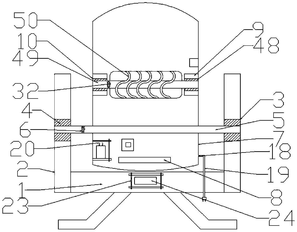
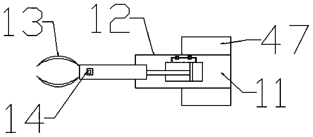
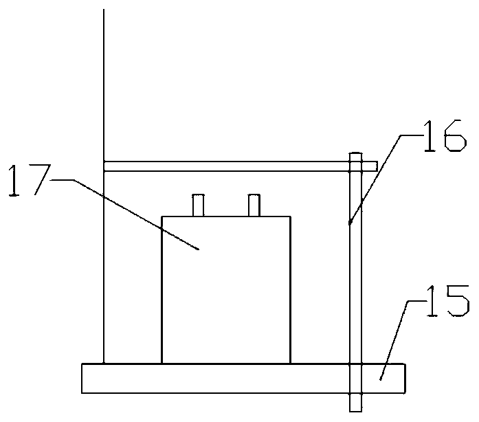
[0022] The present invention is specifically described below in conjunction with accompanying drawing, as Figure 1-6 As shown, a mobile automatic reeling device for optical cables includes a wire take-up bracket 1, the bottom of the wire take-up bracket 1 is provided with a universal wheel device, and the upper part of the wire take-up bracket 1 is fixedly installed on the left and right sides of the wire take-up bracket 1 The take-up baffles 2 on both sides, the take-up circular hole 3 opened in the middle of the take-up baffle 2, the rotary bearing 4 installed in the take-up circular hole 3, the rotary support rod 5 inserted in the rotary bearing 4 , the first rotating motor 6 installed in the rotating pole 5, the wire box 7 installed on the rotating pole 5, the optical cable inlet 8 opened in the middle part of the bottom of the wire box 7, opened in the middle of the top of the wire box 7 The fiber optic cable outlet of the position, the winding block 9 installed in the m...


PUM


Abstract

The invention discloses a mobile optical cable automatic coiling device. The mobile optical cable automatic coiling device comprises a take-up support. The upper part of the take-up support is composed of take-up baffles installed on the left side and the right side of the take-up support respectively, take-up round holes formed in the middle positions of the take-up baffles, rotary bearings installed in the take-up round holes, a rotary supporting rod installed in the rotary bearings in an inserted manner, a first rotary motor installed in the rotary supporting rod, a take-up box installed onthe rotary supporting rod, an optical cable inlet formed in the middle of the lower part of the take-up box, an optical cable outlet formed in the middle of the top of the take-up box, coiling blocksinstalled in the middle of the left side and in the middle of the right side of the interior of the take-up box, coiling holes formed in the middles of the winding blocks, coiling rotation bearings installed in the coiling holes, a coiling rod installed in the coiling rotation bearings in an inserted manner, a coiling thread barrel installed on the coiling rod, a second rotary motor installed inthe coiling rod, and a limiting device installed on the upper part of the coiling block on the right side of the interior of the take-up box together.

Description

technical field [0001] The invention relates to the field of optical cable equipment, in particular to a mobile automatic winding device for optical cables. Background technique [0002] At present, the winding device for the optical cable is still in the state of manual winding, which greatly increases the working time and reduces the work efficiency, so a new type of automatic winding device is needed to solve the above problems. Contents of the invention [0003] The purpose of the present invention is to solve the above problems, and a mobile optical cable automatic winding device is designed. [0004] To achieve the above object, the technical solution of the present invention is a mobile automatic reeling device for optical cables, including a take-up support, the lower part of the take-up support is provided with a universal wheel device, and the upper part of the take-up support is fixedly installed on the take-up The take-up baffles on the left and right sides of...

Claims


Application Information

Patent Timeline
Patent Type & Authority Patents(China)
IPC IPC(8): B65H54/553B65H54/72B65H54/70B65H54/74
CPCB65H54/553B65H54/70B65H54/72B65H54/74B65H2701/32
Inventor 卢敏杰
Owner KINGSIGNAL OPTICAL FIBER & CABLE GANZHOU CO LTD
Why Eureka
Try Eureka