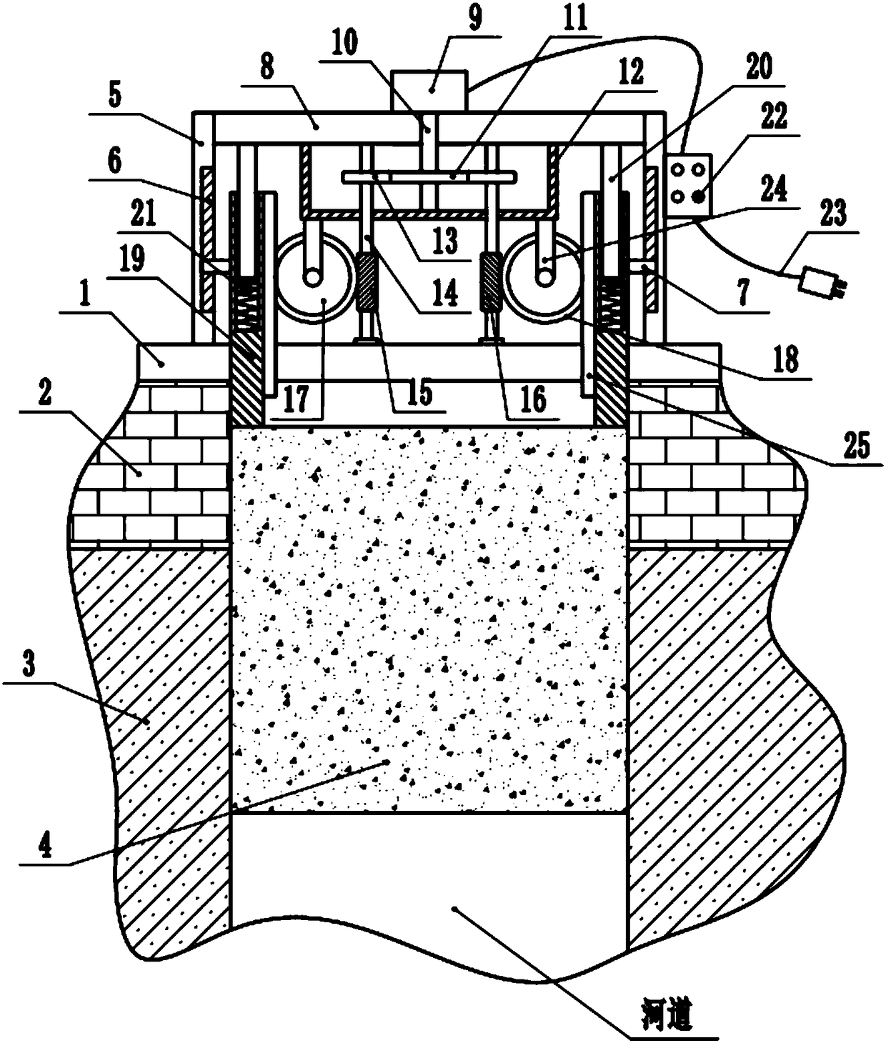
Gate device for hydraulic engineering and using method thereof

A technology for water conservancy projects and gates, which is applied in water conservancy projects, sea area projects, coastline protection, etc. It can solve the problems of screw exposure, equipment size increase, and difficult maintenance, etc., and achieve the effects of increased reliability, simple operation, and reasonable structure

Inactive Publication Date: 2018-09-28
河南正海实业有限公司 +18
View PDF6 Cites 8 Cited by
  • Summary
  • Abstract
  • Description
  • Claims
  • Application Information

AI Technical Summary

Problems solved by technology

[0003] In the field of water conservancy, gate devices are widely used to control the water flow of water supply and drainage. Existing gate devices often use screw drive to adjust the height of the gate plate to adjust the flow rate. Since the weight of the gate plate is often large, it is easy to lose weight. It is easy to cause pressure damage to the screw drive pair, especially in the case of impact, and the smooth operation of these gate plates is often poor and prone to load fluctuations, resulting in impact on the transmission system, which is harmful to the equipment The operation causes safety hazards. At the same time, in order to achieve the required height of the gate plate lifting, the height of the screw must have a size that matches the lift height of the gate plate. This makes the height of the screw rod or the overall length larger, resulting in an increase in the overall size of the equipment. This increases the cost and makes maintenance more difficult. However, if the screw rod is protruded separately from the entire equipment casing, the screw rod is often exposed, which causes the screw rod to be damaged by the external environment and affects the service life, and affects the appearance of the overall equipment and is difficult to maintain.

Method used


Image

  • Gate device for hydraulic engineering and using method thereof
  • Gate device for hydraulic engineering and using method thereof
  • Gate device for hydraulic engineering and using method thereof

Examples


Embodiment Construction

[0022] It should be noted that, in the case of no conflict, the embodiments of the present invention and the features in the embodiments can be combined with each other.

[0023] In describing the present invention, it should be understood that the terms "center", "longitudinal", "transverse", "upper", "lower", "front", "rear", "left", "right", " The orientations or positional relationships indicated by "vertical", "horizontal", "top", "bottom", "inner" and "outer" are based on the orientations or positional relationships shown in the drawings, and are only for the convenience of describing the present invention and Simplified descriptions, rather than indicating or implying that the device or element referred to must have a particular orientation, be constructed and operate in a particular orientation, and thus should not be construed as limiting the invention. In addition, the terms "first", "second", etc. are used for descriptive purposes only, and should not be understood ...


PUM


Abstract

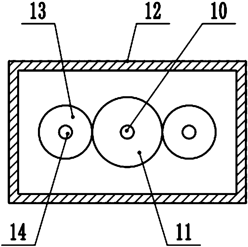
The invention discloses a gate device for hydraulic engineering. The gate device comprises a fixed bottom plate, wherein fixed racks are mounted on the two sides of the upper end of the fixed bottom plate; a top plate is mounted between the top ends of the fixed racks; a driving motor is mounted in the middle part of the upper end of the top plate; a driving shaft is mounted at the lower end of the driving motor; the top plate arranged at the lower end of the driving shaft is connected with a driving gear; the two ends of the driving gear are separately meshed with driven gears; a corresponding rotating shaft is mounted in the middle of each of the driven gears; a left rotating worm gear is mounted in the middle part of the lower end of the left-sided rotating shaft; a right rotating wormgear is mounted in the middle part of the lower end of the right-sided rotating shaft; the left end of the left rotating worm gear and the right end of the right rotating worm gear are separately meshed with rotating worm gears; and rotating gears are mounted on the coaxial positions of the middle parts of the front ends of the rotating worm gears. The invention also discloses a using method of the gate device. Under a driving effect of the driving motor, a gate plate is lifted to an expected position and is stopped; and the gate is moved downwards under a meshed action of the rotating gears and the lifting racks. According to the gate device and the using method of the gate device, the phenomenon that lifting of the gate is realized by utilizing screw transmission is avoided, and the reliability of the whole gate is improved.

Description

technical field [0001] The invention relates to the technical field of water conservancy engineering, in particular to a gate device for water conservancy engineering and a using method thereof. Background technique [0002] Water conservancy projects are projects built to control and allocate natural surface water and groundwater to achieve the purpose of eliminating harm and rejuvenating profits. Also known as water engineering. Water is an indispensable precious resource for human production and life, but its natural state does not fully meet human needs. Only by building water conservancy projects can water flow be controlled, floods prevented, and water volume adjusted and distributed to To meet the needs of people's life and production for water resources, water conservancy projects need to build different types of hydraulic structures such as dams, dikes, spillways, sluices, water inlets, channels, water crossings, raftways, and fishways to achieve their goals. [0...

Claims


Application Information

Patent Timeline
Patent Type & Authority Applications(China)
IPC IPC(8): E02B7/36
Inventor 郭二旺吴世强彭发运王文婷郭乙霏曹兰英杨静周魏波成文明李海波成浩李辉张鹏冲李恒琪牛鹏云郭正林牛鹏程李丽娟
Owner 河南正海实业有限公司
Why Eureka
Try Eureka