
Centrifugal block clamping block transmission

A technology of centrifugal block and transmission, which is applied in the direction of vehicle gearbox, gear transmission, transmission control, etc., can solve the problems of low reliability, complex structure, high technical cost, etc., and achieve the effect of simple structure and good use effect

Inactive Publication Date: 2018-09-28
HANGZHOU FUYANG XINYUAN NEW ENERGY CO LTD
View PDF0 Cites 1 Cited by
  • Summary
  • Abstract
  • Description
  • Claims
  • Application Information

AI Technical Summary

Problems solved by technology

[0002] At present, the transmission gears commonly used in transmissions are all above three gears. For the two-speed transmissions required in equipment that only needs two gears to change gears, either the structure is complicated or the reliability is low. The technical cost required for a two-speed transmission is very high, so it is necessary to design a transmission with only two gears

Method used


Image

  • Centrifugal block clamping block transmission
  • Centrifugal block clamping block transmission
  • Centrifugal block clamping block transmission

Examples


specific Embodiment approach

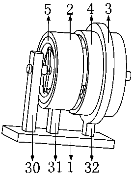
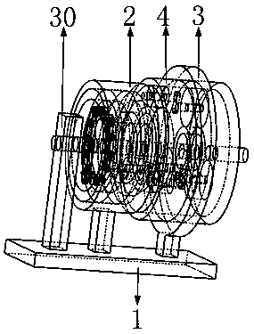
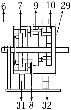
[0044]Specific embodiments: when people use the transmission designed by the present invention, when the input shaft 6 rotates, the input shaft 6 rotates to drive the drive plate 20 to rotate around the axis of the input shaft 6, and the drive plate 20 rotates to drive the arc bar 21 to rotate. When the rotation speed of the arc bar 21 is small, the centrifugal block is less affected by the centrifugal force, and the arc bar 21 and the fixed shaft disc 18 are still in a clamped state, and the arc bar 21 will drive the fixed shaft disc 18 to rotate; the fixed shaft disc 18 drives the third fixed shaft 19 to rotate, and the third fixed shaft 19 rotates through the second one-way ring 15 to drive the second sun gear 17 to rotate; the second sun gear 17 rotates to drive the second planetary gear 10 to rotate; the second planetary gear 10 rotates Drive the inner ring gear 4 to rotate; the inner ring gear 4 drives the output shaft 13 to rotate; that is, the rotation of the input shaf...


PUM


Abstract

The invention belongs to the technical field of transmissions and particularly relates to a centrifugal block clamping block transmission. The centrifugal block clamping block transmission comprises an installing plate, a drum wheel, an input shaft, a Z-shaped ring and an output shaft; when the input shaft rotates, a driving plate rotates and drives arc-shaped strips to rotate; when the rotating speed of the arc-shaped strips is small, the effect of the centrifugal force borne by centrifugal blocks is small; the arc-shaped strips can drive a fixed shaft disk to rotate, and a third fixed shaft,a second one-way ring, a second sun gear and a second planet gear rotate and drive an inner gear ring to rotate; the inner gear ring drives the output shaft to rotate; when the arc-shaped strips moveat a high speed, in the moving process of the first centrifugal block, when the first centrifugal block makes contact with the drum wheel, the first centrifugal block can perform friction with the drum wheel; the arc-shaped strips drive the drum wheel to rotate through friction of the first centrifugal block and the drum wheel; a Z-shaped wheel rotates, and due to rotation of a first one-way ringand a first sun gear, a first planet gear drives the inner gear ring to rotate; the inner gear ring drives the output shaft to rotate; and a simple structure is used, and the beneficial effect of two-gear transmission is achieved.

Description

technical field [0001] The invention belongs to the technical field of transmissions, in particular to a centrifugal block block transmission. Background technique [0002] At present, the transmission gears commonly used in transmissions are all above three gears. For the two-speed transmissions required in equipment that only needs two gears to change gears, either the structure is complicated or the reliability is low. The technical cost required for the two-speed transmission is very high, so it is necessary to design a transmission with only two gears. [0003] The present invention designs a centrifugal block block transmission to solve the above problems. Contents of the invention [0004] In order to solve the above-mentioned defects in the prior art, the present invention discloses a centrifugal block block transmission, which is realized by adopting the following technical solutions. [0005] A centrifugal block block transmission, characterized in that it incl...

Claims


Application Information

Patent Timeline
Patent Type & Authority Applications(China)
IPC IPC(8): F16H3/46F16H57/023
CPCF16H3/46F16H57/023F16H63/30F16H2200/0034F16H2200/2007F16H2200/2035
Inventor 李永建
Owner HANGZHOU FUYANG XINYUAN NEW ENERGY CO LTD
Learn More