Vehicle torsion beam axle

A tie-rod, axle technology, used in vehicle components, interconnection systems, suspensions, etc., can solve problems such as the adverse effects of axle rotation performance and the wheel center being too far away.

Active Publication Date: 2018-09-28
BAYERISCHE MOTOREN WERKE AG
View PDF7 Cites 3 Cited by
  • Summary
  • Abstract
  • Description
  • Claims
  • Application Information

AI Technical Summary

Problems solved by technology

However, the problem arises that the length of the trailing rods is limited for structural space reasons, so that the longitudinal poles cannot be too far from the center of the wheel
In addition, the necessary large length of the trailing rods has a negative effect on the self-rotating behavior of the axle under lateral forces

Method used


Image

  • Vehicle torsion beam axle
  • Vehicle torsion beam axle
  • Vehicle torsion beam axle

Examples


Embodiment Construction

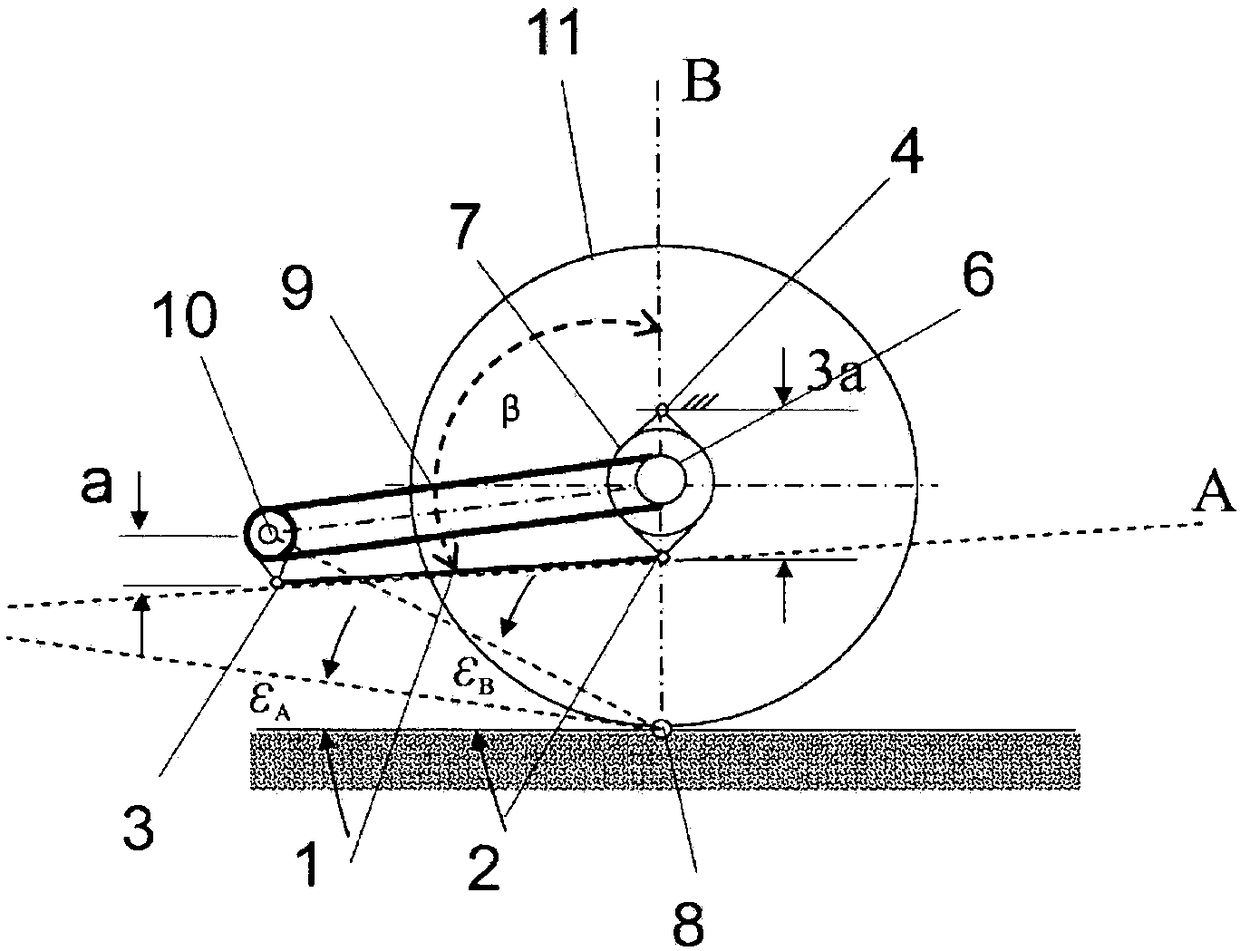
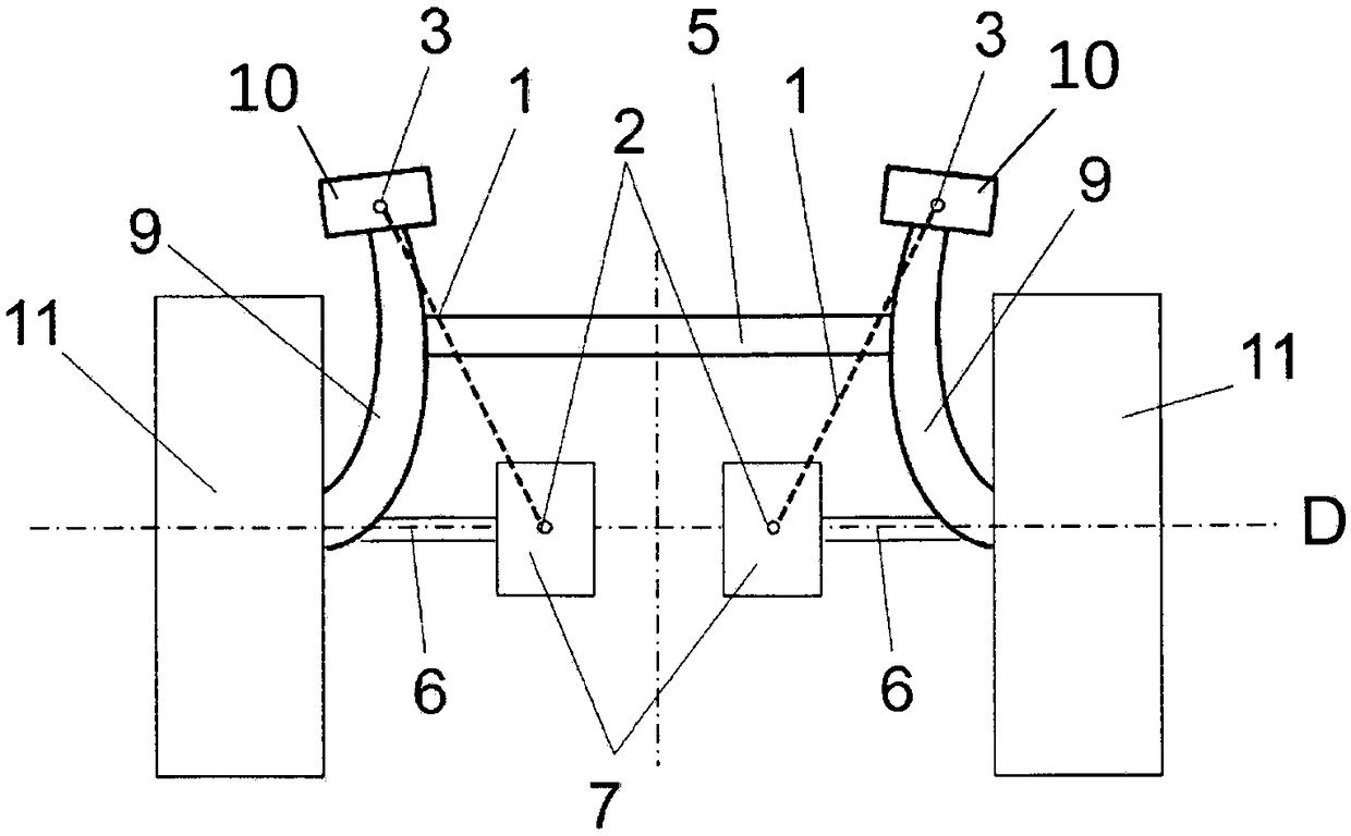
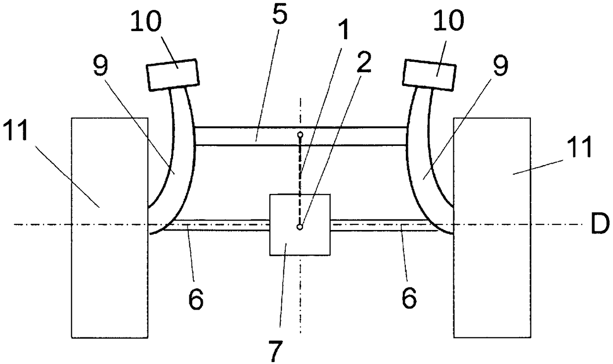
[0027] figure 1 The combined tie-rod axle of a vehicle according to the invention is described in a side view of the vehicle. Visible here is one of the two trailing arms 9 , a drive 7 , which drives at least one wheel 11 , which is guided by the combined tie-rod axle, via the drive shaft 6 . The transverse profile connecting the two trailing arms 9 is not shown in this view. Here, in the designed position, the drive unit 7 is supported on the body via bearings 4 directly adjacent to the common axis of rotation D and has a rotational degree of freedom about an axis parallel to the common axis of rotation D of the wheels 11 . According to the invention, said rotational degree of freedom is supported by a oscillating support 1 . In this case, the pivot support 1 is mounted via a bearing 2 on the drive 7 and via the other bearing 3 on the trailing rod 9 . During springing in and springing out, the drive device 7 is caused to perform a rotational movement about the vehicle tran...


PUM


Abstract

The invention relates to a vehicle torsion beam axle comprising two longitudinal links, a transverse profiled element that connects the longitudinal links, and a drive unit which drives, via an inputshaft, at least one of the wheels guided by the torsion beam axle and which is mounted in the immediate vicinity of the common axis of rotation of the wheels in the design position. The drive unit ismounted on the vehicle body in such a way as to be rotatable about an axis running parallel to the common axis of rotation of the wheels, and said degree of rotational freedom is aided by a pivoted support.

Description

technical field [0001] The invention relates to a combined tie-bar axle (Verbundlenkerachse, composite tie-rod axle) of a vehicle according to the preamble of claim 1 , which has two trailing arms and a transverse profile connecting the trailing arms. Regarding the prior art, see for example DE 10 2011 005 625 A1 and FR 29 62 375 A1. Background technique [0002] It is known from the prior art to form a rear axle, in particular in front-wheel drive double-track vehicles. In this case, the wheel suspension comprises two trailing arms oriented substantially in the direction of travel of the vehicle, which are connected to each other near their front body-side bearing points via an at least slightly twistable transverse profile. Combined tie-rod axles are usually designed as non-driven axles / axles, since otherwise the cardan or articulated shaft of the drive train leading from the vehicle's drive motor, which is usually located in the front area of ​​the vehicle and is designe...

Claims


Application Information

Patent Timeline
Patent Type & Authority Applications(China)
IPC IPC(8): B60G21/05B60K1/00B60K7/00
CPCB60G21/051B60G2200/422B60G2204/18B60G2204/19B60G2204/421B60G2204/422B60G2300/50B60G2800/014B60G2800/18B60G2800/22B60K7/0007B60K2001/001B60K2007/0038B60K2007/0053B60K2007/0092
Inventor L·泽塔勒尔A·普鲁克纳M·达斯勒
Owner BAYERISCHE MOTOREN WERKE AG
Why Eureka
Try Eureka