
A Full Hadamard Matrix Coding Imaging Method

An imaging method and matrix coding technology, which are applied in the coding field of coding imaging, can solve the problem of insufficient improvement of the signal-to-noise ratio, and achieve the effect of solving the impossibility and increasing the signal-to-noise ratio.

Active Publication Date: 2020-09-11
NANJING UNIV OF SCI & TECH
View PDF10 Cites 0 Cited by
  • Summary
  • Abstract
  • Description
  • Claims
  • Application Information

AI Technical Summary

Problems solved by technology

[0006] Aiming at the problem that the existing cyclic matrix encoding method does not increase the signal-to-noise ratio sufficiently, the present invention proposes a full Hadamard matrix encoding imaging method, which indirectly realizes the theoretically optimal encoding matrix encoding and further improves the signal-to-noise ratio. Compare

Method used


Image

  • A Full Hadamard Matrix Coding Imaging Method
  • A Full Hadamard Matrix Coding Imaging Method
  • A Full Hadamard Matrix Coding Imaging Method

Examples


Embodiment

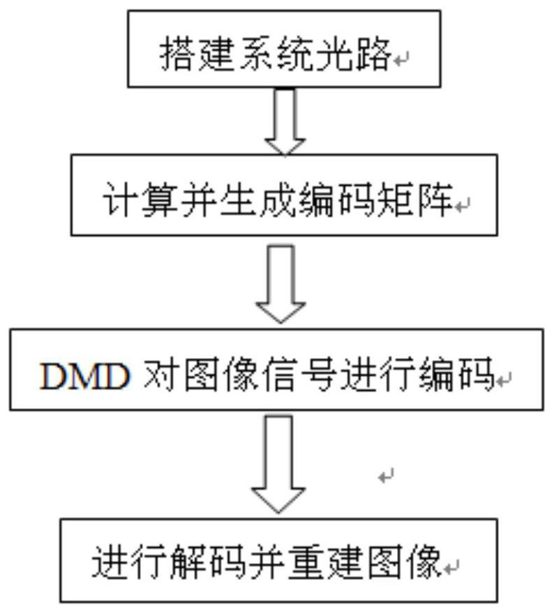
[0041] Step 1: Build the optical path of the imaging system. The optical path of the imaging system is a common optical path. The light enters the optical path from the objective lens, and then irradiates the digital micromirror device DMD through lens focusing. The digital micromirror device DMD modulates the optical path according to the encoding method of Hadamard positive matrix and Hadamard negative matrix. , through the focusing lens to focus on the single-point detector, the signal of the single-point detector is transmitted to the PC for calculation after the signal processor, and the image is reconstructed.

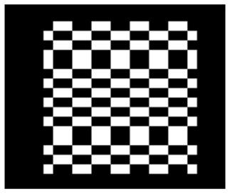
[0042] Step 2: After the optical path is built, use matlab to calculate and generate Hadamard positive matrix and Hadamard negative matrix. Hadamard positive matrix and Hadamard negative matrix can choose different matrix orders according to the situation. In this embodiment, a 256-order matrix is ​​used for encoding, and the 256-order Hadamard matrix H 256 As ...


PUM


Abstract

The invention proposes a full Hadamard matrix coding imaging method. The +1 and ‑1 elements in the Hadamard matrix are extracted respectively through matrix operations, so that the Hadamard matrix can be split into Hadamard positive matrix and Hadamard negative matrix, which can be realized in the optical path, and Hadamard positive matrix and Hadamard matrix are used The Hadamard negative matrix encodes the image signal; when decoding, the measurement value obtained by Hadamard positive matrix encoding is subtracted from the measurement value obtained by Hadamard negative matrix encoding, and then the image is reconstructed through matrix operation. The method of the invention realizes the Hadamard matrix in the optical path modulation, and greatly improves the imaging sensitivity and signal-to-noise ratio.

Description

technical field [0001] The invention belongs to the technical field of weak signal detection and imaging, and in particular relates to an encoding method for encoding imaging. Background technique [0002] Encoded imaging solves the problem of detection and imaging of low-light signals. Coded imaging uses digital micromirror device DMD to perform pixel-level combined measurement of image signals in the optical system, and the code matrix that controls the flipping of digital micromirror device DMD determines the combined measurement method. [0003] At present, the widely used encoding matrix is ​​a circulant matrix, which is transformed from the Hadamard matrix. However, the optimal encoding matrix in theory is Hadamard matrix. Hadamard matrix is ​​composed of +1 and -1 elements, which cannot be realized in the actual optical path, while the circular matrix is ​​composed of +1 and 0 elements, which is easy to realize in the actual optical path, so Currently, circulant mat...

Claims


Application Information

Patent Timeline
Patent Type & Authority Patents(China)
IPC IPC(8): H04N5/232
CPCH04N23/80
Inventor 韩静吴传奇岳江张毅柏连发
Owner NANJING UNIV OF SCI & TECH
Learn More