Pneumatic soft clamp

A pneumatic, fixture technology, used in chucks, manufacturing tools, manipulators, etc., can solve the problems of short service life of the anti-skid layer, easy scratching on the surface of the workpiece, troublesome operation, etc., to prevent scratches on the surface of the workpiece or damage to the workpiece, The effect of convenient daily maintenance and low manufacturing cost

Inactive Publication Date: 2018-10-09
广东顺德泽洋机电制造有限公司
View PDF0 Cites 12 Cited by
  • Summary
  • Abstract
  • Description
  • Claims
  • Application Information

AI Technical Summary

Problems solved by technology

[0002] At present, in the fixtures used by robots, hard jaws are generally used to clamp the workpiece; it has the following defects: 1. The jaws are generally made of hard materials, and the jaws and the workpiece during the clamping process The rigid contact between them will cause the surface of the workpiece to be easily scratched or directly crush the workpiece (especially the easily damaged workpiece, such as: plastic parts, foam parts, wood parts, etc.); the existing solution is to add an anti-skid layer on the jaws To increase friction and avoid rigid contact, but this method will lead to increased costs, and the service life of the anti-skid layer is short, it needs to be replaced or maintained regularly, and the operation is troublesome; 2. To avoid excessive clamping force of the hard jaws To crush the workpiece, it is necessary to accurately control the clamping force of the jaws, which requires technicians to do multiple tests to obtain the best clamping force; there are also sensing devices to control the magnitude of the clamping force, but increase the induction The device will lead to increased cost, complex structure, and regular maintenance of the induction device; 3. In order to achieve the clamping effect, the jaws are generally set in moving, swinging and other activities, so it is necessary to reserve enough space for the jaws to move, causing the clamp Larger space required for work

Method used


Image

  • Pneumatic soft clamp
  • Pneumatic soft clamp
  • Pneumatic soft clamp

Examples


no. 1 example

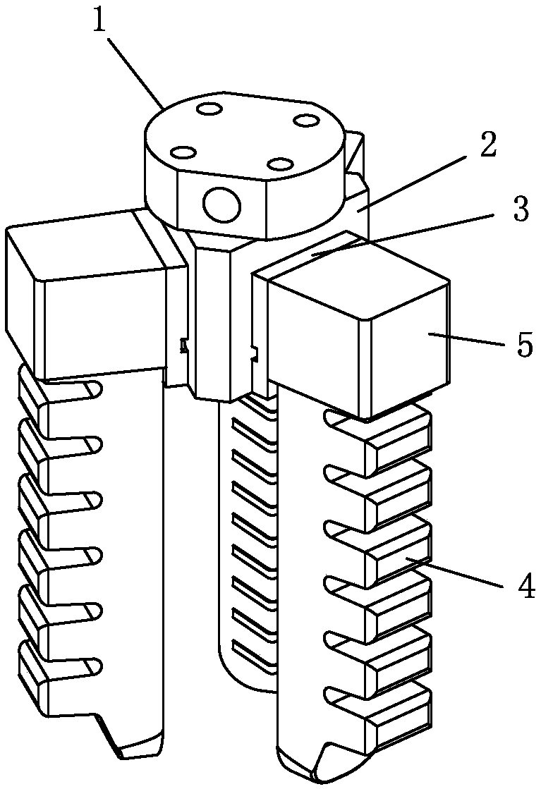
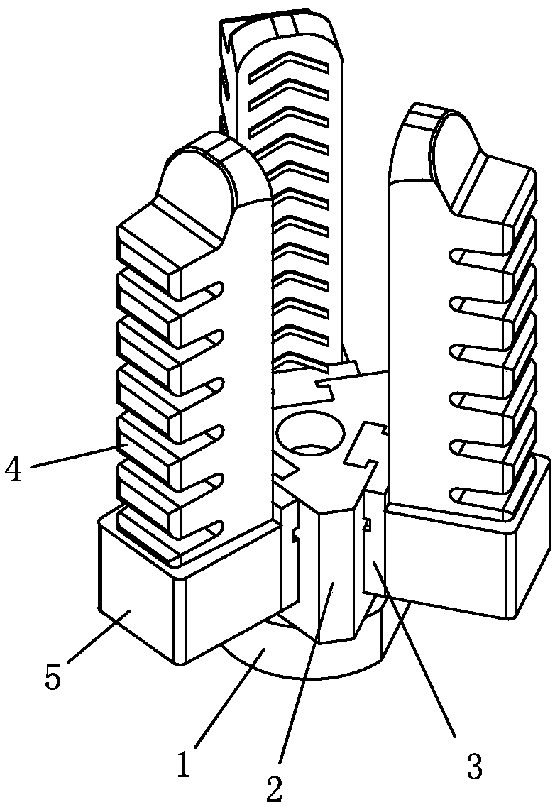
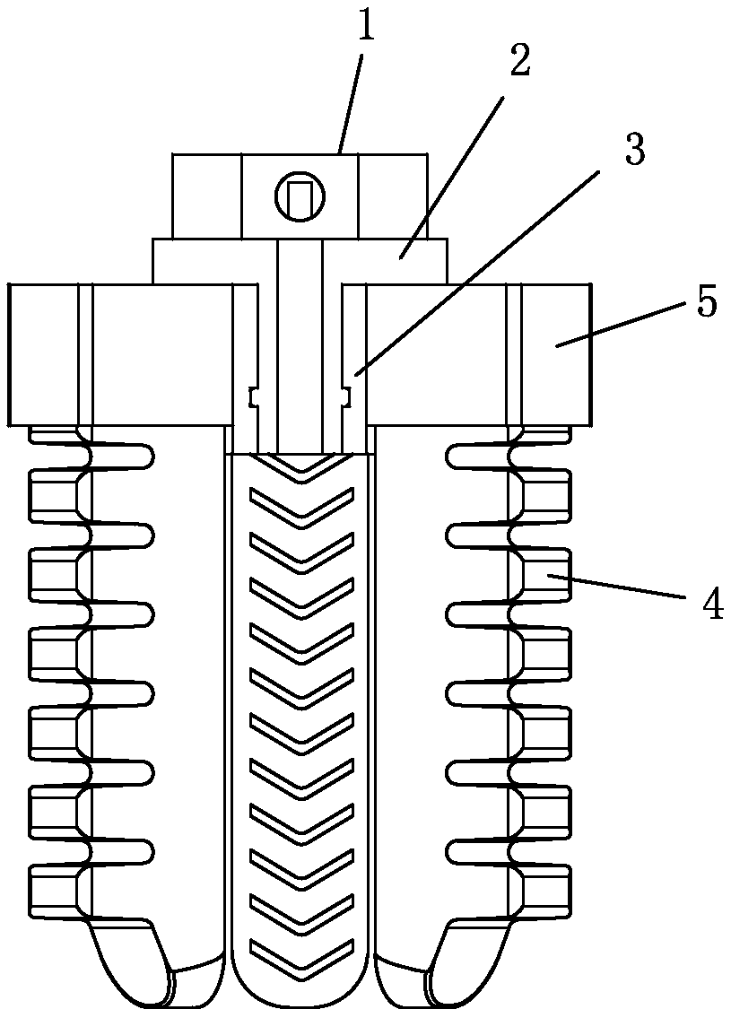
[0032] see Figure 1-Figure 10 , the pneumatic soft clamp includes a clamp base 2, and three soft jaws 4 are evenly distributed in a ring around the clamp base 2, and each soft jaw 4 is integrally formed by a soft material (rubber); The inner side of the soft jaw 4 is provided with a bendable clamping side 401, and the outer side is provided with a retractable telescopic side 402, and the clamping side 401 is opposite to the telescopic side 402; the soft jaw 4 is hollowed out with a comb-shaped air bag; In the initial or working state, the airbag is inflated, the clamping side 401 is flat or turned inward, the telescopic side 402 is stretched, the soft gripper 4 is straight or turned inward as a whole, and the gripping side 401 of two or more soft grippers 4 is in common Clamp the workpiece to achieve the effect of clamping the workpiece; in the open state, the air bag is vacuumed, the clamping side 401 is turned outward, the telescopic side 402 is contracted, and the soft jaw...

no. 2 example

[0041] see Figure 11-Figure 16 , This pneumatic soft clamp is different from the first embodiment in that: there are six soft clamping jaws 4 evenly distributed around the clamp base 2; in addition, the soft clamping jaws 4 can also be set to four or five , seven or eight, etc.

[0042] Other parts not described are the same as those of the first embodiment, and will not be described in detail here.


PUM


Abstract

The invention relates to a pneumatic soft clamp. The pneumatic soft clamp comprises a clamp substrate, wherein two or more soft clamping jaws are annularly distributed on the clamp substrate, and eachsoft clamping jaw is integrally formed by a soft material; each soft clamping jaw is provided with a bendable clamping side and a stretchable stretching side, and the clamping side and the stretchingside are arranged opposite to each other; an air bag is arranged in each soft clamping jaw; in an initial state or a working state, the air bags suck air, the clamping sides are smooth or overturn inward, the stretching sides are relaxed, the soft clamping jaws are straight integrally or overturn inward, and the clamping sides of the two or more soft clamping jaws clamp a workpiece jointly; and in a stretching state, the air bags are vacuumized, the clamping sides overturn outward, the stretching sides shrink, and the soft clamping jaws stretch outward integrally. The pneumatic soft clamp hasthe characteristics of being simple in design, reasonable in structure, high in universality, reliable in performance, low in cost, convenient to maintain, easy to assemble and reliable and stable inclamping effect.

Description

technical field [0001] The invention relates to a robot clamp, in particular to a pneumatic soft clamp. Background technique [0002] At present, in the fixtures used by robots, hard jaws are generally used to clamp the workpiece; it has the following defects: 1. The jaws are generally made of hard materials, and the jaws and the workpiece during the clamping process The rigid contact between them will cause the surface of the workpiece to be easily scratched or directly crush the workpiece (especially the easily damaged workpiece, such as: plastic parts, foam parts, wood parts, etc.); the existing solution is to add an anti-skid layer on the jaws To increase friction and avoid rigid contact, but this method will lead to increased costs, and the service life of the anti-skid layer is short, it needs to be replaced or maintained regularly, and the operation is troublesome; 2. To avoid excessive clamping force of the hard jaws To crush the workpiece, it is necessary to accura...

Claims


Application Information

Patent Timeline
IPC IPC(8): B25J15/00B25J15/10
CPCB25J15/0023B25J15/10
Inventor 林裕强
Owner 广东顺德泽洋机电制造有限公司
Why Eureka
Try Eureka