
A device and method for detecting the air tightness of an air path

An airtightness and gas detection technology, which is applied in the direction of measuring the increase and decrease rate of the fluid, using liquid/vacuum degree to measure the liquid tightness, etc., can solve the problems of inaccurate measurement parameters, treatment delay, patient injury, etc.

Inactive Publication Date: 2018-10-09
EDAN INSTR
View PDF8 Cites 3 Cited by
  • Summary
  • Abstract
  • Description
  • Claims
  • Application Information

AI Technical Summary

Problems solved by technology

In order to ensure the accuracy of the measurement, the airtightness of the entire gas path of the module must be kept good. Poor airtightness will cause inaccurate measurement parameters such as: low value, abnormal waveform shape, and the introduction of other interfering gases other than the target gas. Further affecting the measurement results, deviations in measurement accuracy are likely to cause delays in treatment and cause serious harm to patients
[0003] In the prior art, there is no equipment that can detect the air tightness of the gas path of the side flow monitoring equipment at any time

Method used


Image

  • A device and method for detecting the air tightness of an air path
  • A device and method for detecting the air tightness of an air path

Examples


Embodiment Construction

[0022] Embodiments of the present invention are described in detail below, examples of which are shown in the drawings, wherein the same or similar reference numerals designate the same or similar elements or elements having the same or similar functions throughout. The embodiments described below by referring to the figures are exemplary only for explaining the present invention and should not be construed as limiting the present invention.

[0023] In describing the present invention, it should be understood that the terms "center", "longitudinal", "transverse", "upper", "lower", "front", "rear", "left", "right", " The orientations or positional relationships indicated by "vertical", "horizontal", "top", "bottom", "inner" and "outer" are based on the orientations or positional relationships shown in the drawings, and are only for the convenience of describing the present invention and Simplified descriptions, rather than indicating or implying that the device or element refe...


PUM


Abstract

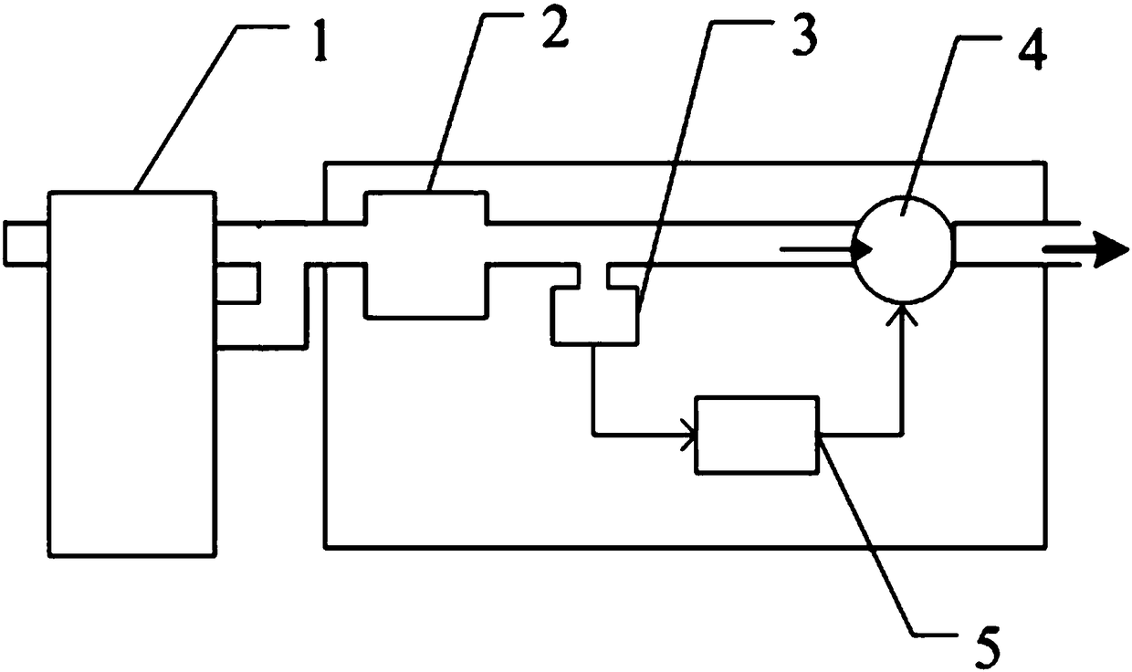
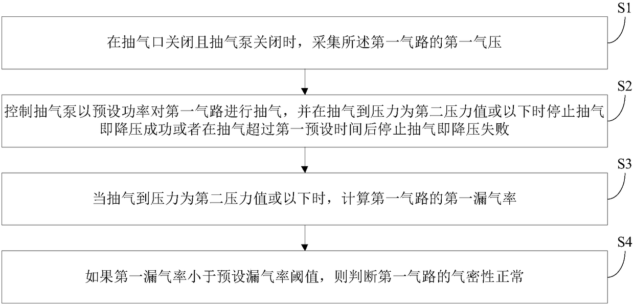
The invention discloses a device and method for detecting the air tightness of an air path. The device includes a dehydration device, an air chamber and a suction pump which are arrange in sequence, the dehydration device is provided with an air inlet, a pressure sensor is installed on the air path between the air chamber and the suction pump, the device also includes a control system, the controlsystem is connected with the pressure sensor and the suction pump, when the air inlet is closed, whether gas tightness of a first air path meets the requirements is determined by a plurality of pressure values of the first air path when the suction pump is in different operation states, and the first air path is the air path between the dehydration device and the suction pump. The device has theadvantages that: detection can be performed on the air tightness of the air path momentarily, and the detection result can be fed back.

Description

technical field [0001] The invention relates to the field of airtightness detection, in particular to a device and method for detecting the airtightness of a gas path. Background technique [0002] At present, the continuous non-invasive measurement of patient's respiratory gas by using the monitor has been widely used in clinical practice. According to different gas sampling methods, the monitoring of patients' breathing gas is mainly divided into two types: mainstream and side flow, especially the side flow method is the most widely used clinically. In order to ensure the accuracy of the measurement, the airtightness of the entire gas path of the module must be kept good. Poor airtightness will cause inaccurate measurement parameters such as: low value, abnormal waveform shape, and the introduction of other interfering gases other than the target gas. Further affecting the measurement results, deviations in measurement accuracy are likely to cause delays in treatment and ...

Claims


Application Information

Patent Timeline
Patent Type & Authority Applications(China)
IPC IPC(8): G01M3/26
Inventor 张微朱振营
Owner EDAN INSTR
Learn More