Speed reducing device for preventing traveling in reverse direction

A technology of deceleration device and deceleration belt, which is applied in the directions of roads, road signs, traffic signals, etc., can solve problems such as inability to correctly control vehicles, collision with public equipment, panic of wheel drivers, etc. Effect

Active Publication Date: 2018-10-16
WM MOTOR TECH GRP CO LTD
View PDF5 Cites 4 Cited by
  • Summary
  • Abstract
  • Description
  • Claims
  • Application Information

AI Technical Summary

Problems solved by technology

[0005] The purpose of the present invention is to solve the problem that in the prior art, when the vehicle passes the deceleration belt retrogradely, the vehicle will still pass through the deceleration belt if the wheel blows out, and the tire blowout will easily cause the driver to panic and cannot correctly control the vehicle, which is easy and smooth. The anti-reverse deceleration device is proposed for the collision of vehicles coming in the direction of the vehicle or the serious threat to other public equipment or pedestrians around the vehicle.

Method used


Image

  • Speed reducing device for preventing traveling in reverse direction
  • Speed reducing device for preventing traveling in reverse direction
  • Speed reducing device for preventing traveling in reverse direction

Examples


Embodiment 1

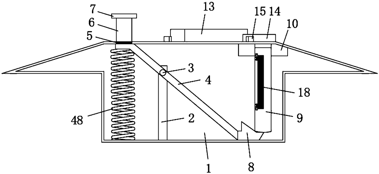
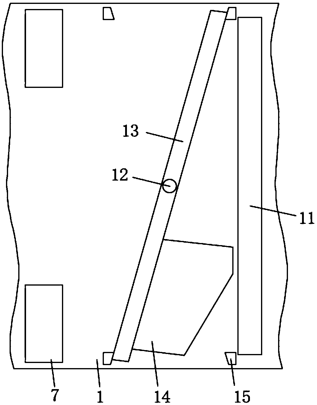
[0033] refer to Figure 1-5 , the anti-reverse deceleration device, including the deceleration belt 1, the interior of the deceleration belt 1 is symmetrically fixedly connected with two turrets 2, the two turrets 2 are jointly rotated and connected with the first rotating shaft 3, and the first rotating shaft 3 is fixedly connected with Rotate the lever 4, and the first rotating shaft 3 runs through the rotating lever 4, one end of the rotating lever 4 is provided with a rubber block 5, the upper end of the rubber block 5 is fixedly connected with a pressing rod 6, and the upper end of the pressing rod 6 runs through the inner wall of the speed reduction belt 1 and The pressing plate 7 is fixedly connected, and the vertical height between the pressing plate 7 and the deceleration belt 1 is one-third of the normal wheel, so that the pressing plate 7 will not contact and affect other parts of the vehicle during the forward process. The other end of the lever 4 is fixedly connec...

Embodiment 2

[0038] refer to Figure 6-9 The difference between this embodiment and Embodiment 1 is that the shielding structure includes a pressure sensor 26, a gear motor 27, a first rotating shaft 28, a first helical gear 29, a second helical gear 30, a second rotating shaft 31, a bar Magnet 32, support frame 33, baffle plate 34, single magnetic pole 35, support plate 36, reinforcing rod 37 and controller 49, pressure sensor 26 is installed on the upper surface of deceleration belt 1, and pressure sensor 26 is positioned at the bar blind hole 11 On the right side, a reduction motor 27 and a controller 49 are installed inside the speed reduction belt 1. The driving end of the reduction motor 27 is fixedly connected with the first rotating shaft 28, and the first rotating shaft 28 is fixedly connected with the first helical gear 29, and the second A rotating shaft 28 runs through the first helical gear 29, the first helical gear 29 is meshed with a second helical gear 30, the second helic...

Embodiment 3

[0042] refer to Figure 10-13 The difference between this embodiment and Embodiment 1 and Embodiment 2 is that the shielding structure includes a second rotating shaft 31, a bar magnet 32, a baffle plate 34, a single magnetic pole 35, a support plate 36, a reinforcing rod 37, and a block 38 , turntable 39, second rotating rod 40, second fixed seat 41, second rotating shaft 42, first gear 43, second gear 44, mounting seat 45, mounting frame 46, reinforcing rib 47, the upper surface of deceleration belt 1 The turntable 39 is attached symmetrically, and the interior of the deceleration belt 1 is fixedly connected with a mounting seat 45, and the mounting seat 45 is rotatably connected with a second rotating shaft 31 through a bearing, and the second rotating shaft 31 is fixedly connected with a bar magnet 32 ​​and a second gear 44. , and the second gear 44 is located above the bar magnet 32, the upper end of the second rotating shaft 31 passes through the second gear 44 and is co...


PUM


Abstract

The invention discloses a speed reducing device for preventing traveling in the reverse direction. The speed reducing device comprises a deceleration strip, two rotating frames are symmetrically and fixedly connected to the inner side of the deceleration strip, a first rotating shaft is connected between the two rotating frames in a rotating mode, and a rotating lever is fixedly connected to the first rotating shaft. The first rotating shaft penetrates through the rotating lever, and a rubber block abuts against one end of the rotating lever. The upper end of the rubber block is fixedly connected with a pressing rod, the upper end of the pressing rod penetrates through the inner wall of the deceleration strip and is fixedly connected with a pressing plate, and the vertical height of the pressing plate and the deceleration strip is one third of the height of a normal wheel. The other end of the rotating lever is fixedly connected with a supporting seat, and an impact plate is arranged at the upper end of the supporting seat in an abutting mode. The speed reducing device has the advantages that vehicles can be effectively prevented from travelling reversely, simple punishment is onlycarried out on vehicles traveling reversely, other normal running vehicles and other public equipment or pedestrians around the vehicles cannot be threatened, and the effect of preventing traveling in the reverse direction is effectively improved.

Description

technical field [0001] The invention relates to the technical field of traffic facilities, in particular to an anti-reverse speed reduction device. Background technique [0002] The speed bump is a traffic facility installed on the road to slow down the passing vehicles. It is generally strip-shaped or dot-shaped. The material is mainly rubber or metal. It is generally yellow and black to attract visual attention and make the road slightly Arched to achieve the purpose of vehicle deceleration, but when the existing speed bumps are actually used, the vibrations to the vehicle are basically the same when vehicles in different directions pass through the speed bumps, and it is impossible to remind and punish the reverse vehicle by strengthening the vibration. [0003] At present, there is a kind of anti-reverse speed bump in France. There are jagged mechanisms hidden inside the speed bump. After opening, these saw teeth will stand up. When you drive the vehicle in the correct d...

Claims


Application Information

Patent Timeline
Patent Type & Authority Applications(China)
IPC IPC(8): E01F9/529E01F13/10
CPCE01F9/529E01F13/105
Inventor 田泽
Owner WM MOTOR TECH GRP CO LTD
Why Eureka
Try Eureka