Oil and gas separator air intake structure and engine

A technology of oil and gas separator and engine, which is applied in the direction of machines/engines, engine components, mechanical equipment, etc., which can solve the problems of low separation efficiency, lack of oil and gas pre-separation chamber, and large working load of oil and gas separator, and achieve the gas intake position High, reduce space size, reduce the effect of overall machine size

Active Publication Date: 2019-12-10
WEICHAI POWER CO LTD
View PDF3 Cites 0 Cited by
  • Summary
  • Abstract
  • Description
  • Claims
  • Application Information

AI Technical Summary

Problems solved by technology

The position of the air intake hole is low, very close to the crankshaft hole and the assembly surface of the oil pan. Due to the movement of the crankshaft, connecting rod and other components, the engine oil returned to the oil pan by the cylinder head and the valve mechanism, and the oil gas in the crankcase are stirred. The oil content in the medium is very high, and there is no oil-gas pre-separation chamber, which may easily cause a large workload of the oil-gas separator and low separation efficiency

Method used


Image

  • Oil and gas separator air intake structure and engine
  • Oil and gas separator air intake structure and engine
  • Oil and gas separator air intake structure and engine

Examples


Embodiment Construction

[0026] Hereinafter, exemplary embodiments of the present disclosure will be described in more detail with reference to the accompanying drawings. Although the drawings show exemplary embodiments of the present disclosure, it should be understood that the present disclosure can be implemented in various forms and should not be limited by the embodiments set forth herein. On the contrary, these embodiments are provided to enable a more thorough understanding of the present disclosure and to fully convey the scope of the present disclosure to those skilled in the art.

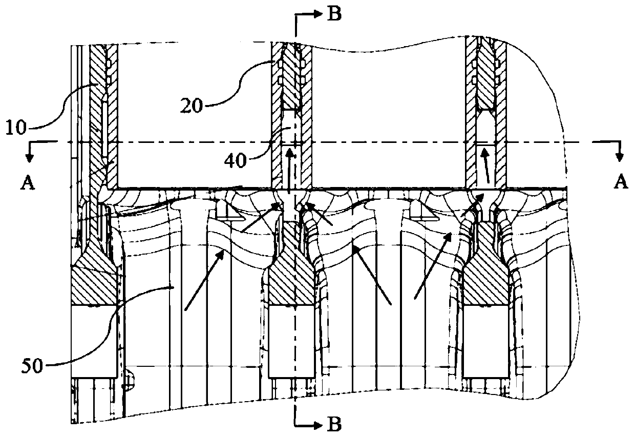
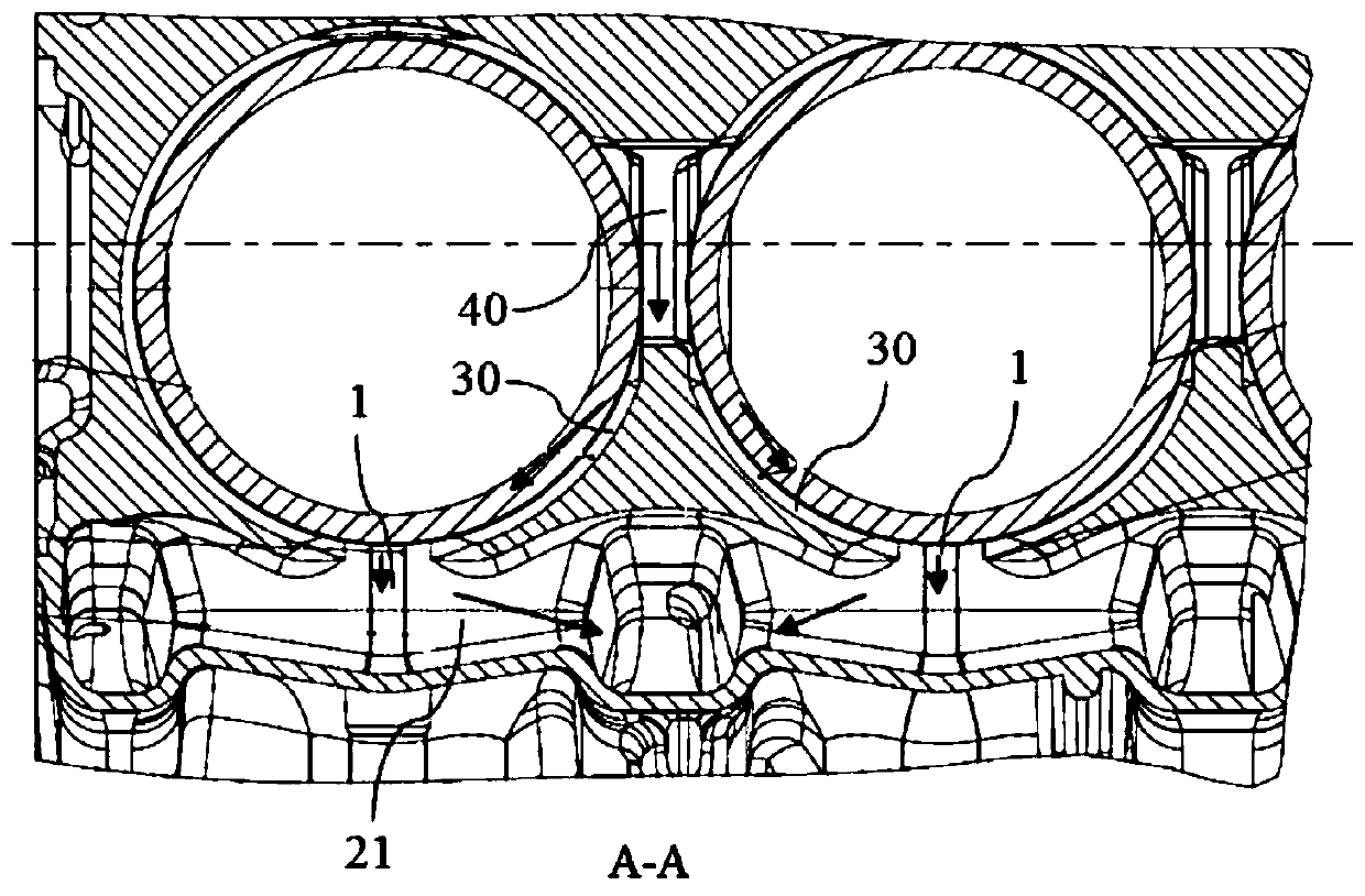
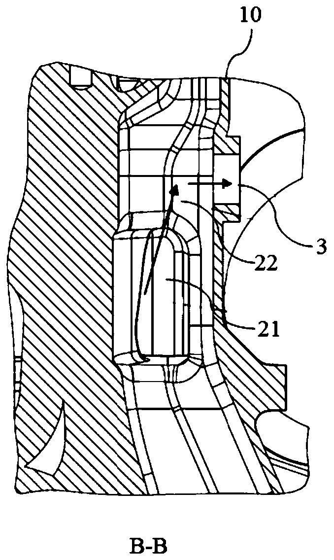
[0027] Figure 1 to Figure 3 It shows a schematic diagram of the gas extraction structure of an oil-gas separator according to an embodiment of the present invention. The direction of the arrow in the figure is the oil and gas path. The cylinder block 10 is the main body of the engine, which connects each cylinder and the crankcase into a whole, such as figure 1 As shown, the cylinder block 10 includes a plurality ...


PUM


Abstract

The invention provides a gas taking structure of an oil-gas separator and an engine. The gas taking structure is arranged on a cylinder body of the engine, the gas taking structure comprises an oil-gas inlet, a gas taking channel arranged in the cylinder body and a gas taking port, the gas taking channel comprises an oil-gas pre-separation cavity and an oil-gas rising cavity which are communicatedwith each other, the oil-gas inlet is arranged at an air inlet end of the oil-gas pre-separation cavity, a gas outlet end of the oil-gas pre-separation cavity is connected with an air inlet end of the oil-gas rising cavity, an air outlet end of the oil-gas rising cavity is connected with the gas taking port, and the gas taking port is arranged at an upper part of the cylinder body and connected with an air inlet of the oil-gas separator; the oil-gas in a crankcase can enter the oil-gas pre-separation cavity through the oil-gas inlet for oil and gas pre-separation, and the pre-separated oil-gas can rise to the gas taking port through the oil-gas rising cavity and enter the oil-gas separator through the gas taking port for oil-gas separation. According to the gas taking structure of the oil-gas separator and the engine of the invention, a pre-separation structure is integrated on the cylinder body, and the gas taking position is high, so that the oil content can be reduced, and the separation efficiency can be improved.

Description

Technical field [0001] The invention relates to the technical field of engine oil and gas separation, in particular to an oil and gas separator gas extraction structure and an engine. Background technique [0002] When the existing oil and gas separator takes gas, the gas is taken directly from the crankcase position on the engine body, and the oil and gas separator is connected through the gas hole. The location of the air hole is low, very close to the crankshaft hole and the assembly surface of the oil pan. Due to the movement of the crankshaft, connecting rod and other parts, the oil in the cylinder head and the valve mechanism return to the oil pan and the oil and gas in the crankcase are stirred. The oil content is very high, and there is no oil and gas pre-separation cavity, which easily causes the oil and gas separator to have a large working load and low separation efficiency. Summary of the invention [0003] The purpose of the present invention is to solve at least one...

Claims


Application Information

Patent Timeline
Patent Type & Authority Patents(China)
IPC IPC(8): F01M13/04
CPCF01M13/04
Inventor 董晓婷张少杰李春锋杜飞飞崔京朋
Owner WEICHAI POWER CO LTD
Why Eureka
Try Eureka