Oil-gas separator and crankcase forced ventilation system with same

An oil and gas separator, oil and gas technology, applied in crankcase ventilation, machine/engine, combustion engine and other directions, can solve the problem of low separation efficiency of oil and gas separator

Active Publication Date: 2022-05-13
WEICHAI POWER CO LTD
View PDF7 Cites 0 Cited by
  • Summary
  • Abstract
  • Description
  • Claims
  • Application Information

AI Technical Summary

Problems solved by technology

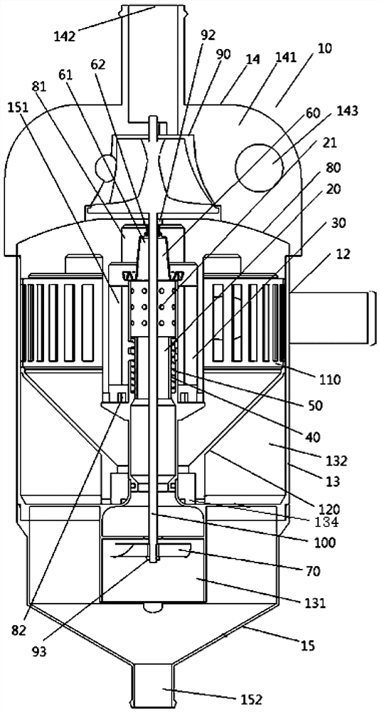
[0006] The main purpose of the present invention is to provide an oil-gas separator and a crankcase forced ventilation system with it, so as to solve the problem that the separation efficiency of the oil-gas separator in the prior art is relatively low

Method used


Image

  • Oil-gas separator and crankcase forced ventilation system with same
  • Oil-gas separator and crankcase forced ventilation system with same
  • Oil-gas separator and crankcase forced ventilation system with same

Examples


Embodiment Construction

[0040] It should be noted that, in the case of no conflict, the embodiments in the present application and the features in the embodiments can be combined with each other. The present invention will be described in detail below with reference to the accompanying drawings and examples.

[0041] It should be pointed out that the following detailed description is exemplary and intended to provide further explanation to the present application. Unless defined otherwise, all technical and scientific terms used herein have the same meaning as commonly understood by one of ordinary skill in the art to which this application belongs.

[0042] It should be noted that the terminology used here is only for describing specific implementations, and is not intended to limit the exemplary implementations according to the present application. As used herein, unless the context clearly dictates otherwise, the singular is intended to include the plural, and it should also be understood that wh...


PUM


Abstract

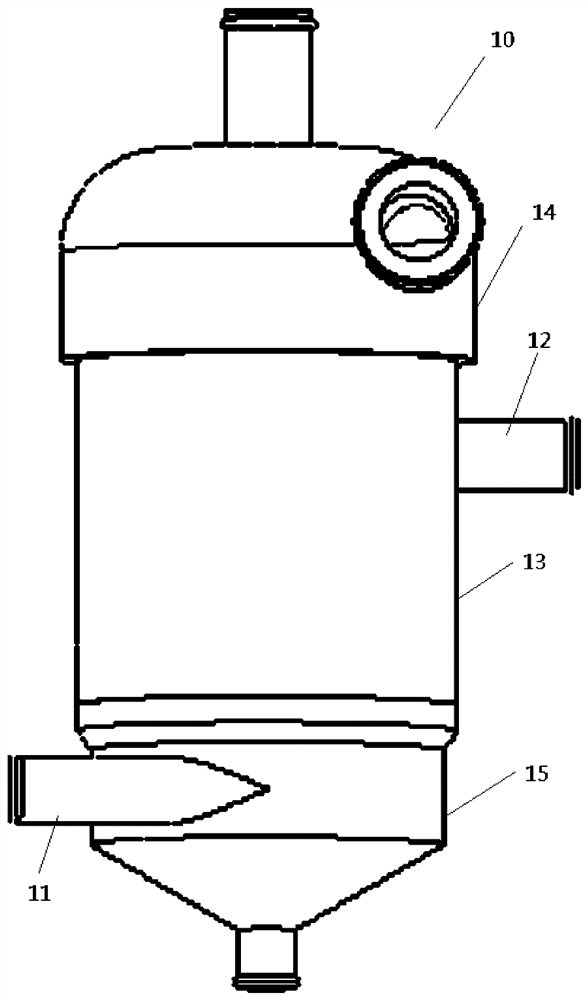
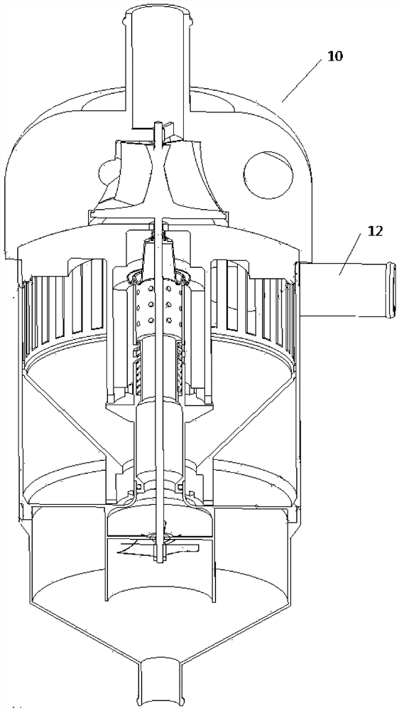
The invention provides an oil-gas separator and a crankcase forced ventilation system with the oil-gas separator, the oil-gas separator comprises a casing and a first gas inlet and a first gas outlet which are arranged on the casing, and the oil-gas separator further comprises a gas inlet pipe arranged in the casing, and a gas outlet pipe arranged in the casing and provided with a first end communicated with the first gas inlet; a plurality of communicating holes are formed in the pipe wall of the air inlet pipe, the communicating holes are sequentially formed in the axial direction of the air inlet pipe, and the air inlet pipe communicates with the first air outlet through the communicating holes; the oil-gas separation piece is arranged in the machine shell, and the oil-gas separation piece is used for separating oil drops in the gas; and the sliding sleeve is arranged in the air inlet pipe, and the sliding sleeve does reciprocating rectilinear motion in the axial direction of the air inlet pipe according to the air inlet amount of the air inlet pipe so as to block different numbers of communicating holes. According to the oil-gas separator, the problem that in the prior art, an oil-gas separator is low in separation efficiency is solved.

Description

technical field [0001] The invention relates to the technical field of automobiles, in particular to an oil-gas separator and a crankcase forced ventilation system having the same. Background technique [0002] The pollutants brought by automobiles not only refer to the combustion pollutants directly discharged from the engine exhaust pipe. The main source of pollutants; also includes crankcase blow-by gas pollutants directly discharged into the atmosphere, the reason is that there is a gap between the piston and the cylinder, part of the mixed gas in the cylinder will flow into the crankcase from the gap, these crankcase blow-by gases must be Release it in time, because excessive accumulation of blow-by gas will cause the pressure in the crankcase to be higher than the allowable value, damage the sealing structure, and cause oil leakage; and when the weather is cold, water vapor and fuel vapor in the blow-by gas in the crankcase will condense and mix into the In the engine...

Claims


Application Information

Patent Timeline
Patent Type & Authority Applications(China)
IPC IPC(8): F01M13/04F01M13/02
CPCF01M13/04F01M13/021F01M2013/0488F01M2013/027Y02T10/12
Inventor 潘洁李卫窦站成张海瑞
Owner WEICHAI POWER CO LTD
Why Eureka
Try Eureka