Vibration reduction base for intelligent equipment

A technology of intelligent equipment and shock-absorbing base, applied in mechanical equipment, engine base, supporting machine, etc., can solve the problem that the fixed base does not have shock-absorbing function and cannot prevent bumps, etc., and achieves the effect of good shock-absorbing effect.

Inactive Publication Date: 2018-10-19
HEFEI SHULI ELECTRONICS INFORMATION TECH CO LTD
View PDF0 Cites 7 Cited by
  • Summary
  • Abstract
  • Description
  • Claims
  • Application Information

AI Technical Summary

Problems solved by technology

The reliability of components, technical design, technological level and technical management jointly determine the reliability index of electronic products. To improve the reliability of prod

Method used


Image

  • Vibration reduction base for intelligent equipment

Examples


Embodiment Construction

[0017] The following will clearly and completely describe the technical solutions in the embodiments of the present invention with reference to the accompanying drawings in the embodiments of the present invention. Obviously, the described embodiments are only some, not all, embodiments of the present invention. All other embodiments obtained by persons of ordinary skill in the art based on the embodiments of the present invention belong to the protection scope of the present invention.

[0018] According to an embodiment of the present invention, a shock-absorbing base for a smart device is provided.

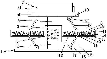
[0019] Such as figure 1 As shown, the shock-absorbing base for smart devices according to the embodiment of the present invention includes a base 1, the upper end of the base 1 is provided with a fixed rod-2, and the upper end of the fixed rod-2 is provided with a sleeve 3, so The upper end of the sleeve 3 is provided with a fixed rod two 4, and the upper end of the fixed rod ...


PUM


Abstract

The invention discloses a vibration reduction base for intelligent equipment. The vibration reduction base comprises a base body. A first fixing rod is arranged at the upper end of the base body. A sleeve is arranged at the upper end of the first fixing rod. A second fixing rod is arranged at the upper end of the sleeve. The upper end of the first fixing rod and the lower end of the second fixingrod are both located in the sleeve. A first spring is arranged at the position, located inside the sleeve, between the first fixing rod and the second fixing rod. The end, away from the sleeve, of thesecond fixing rod is provided with a support plate. The upper end of the support plate is provided with an intelligent equipment body. The two ends of the sleeve are each provided with a connecting plate. Each connecting plate is provided with a limiting groove. A sliding block is arranged in each limiting groove, wherein each sliding block is matched with the corresponding limiting groove. A second spring is arranged at the position, located inside the corresponding limiting groove, of one side of each sliding block. A third spring is arranged at the position, located inside the corresponding limiting groove, of the other side of each sliding block. A first rotating shaft is arranged on each sliding block in a penetrating and inserted manner. Connecting rings are arranged at the two endsof each first rotating shaft in a sleeving manner correspondingly. A first connecting rod is arranged at one side of each connecting ring.

Description

technical field [0001] The invention relates to the field of smart devices, in particular to a shock-absorbing base for smart devices. Background technique [0002] At present, intelligent equipment is a highly automated mechatronic equipment. Due to its complex structure and important role in the system, there are high requirements for the reliability of intelligent equipment. The reliability of components, technical design, technological level and technical management jointly determine the reliability index of electronic products. To improve the reliability of products, it is necessary to grasp the failure laws of products. Vibration occurs when smart devices work, but the existing The fixed base has no shock absorption function and cannot prevent bumps. [0003] Aiming at the problems in the related technologies, no effective solution has been proposed yet. Contents of the invention [0004] In view of the problems in the related art, the present invention propose...

Claims


Application Information

Patent Timeline
IPC IPC(8): F16F15/04F16F15/08F16M5/00
CPCF16F15/04F16F15/08F16M5/00
Inventor 蔡忠芳
Owner HEFEI SHULI ELECTRONICS INFORMATION TECH CO LTD
Why Eureka
Try Eureka