A flue gas dust removal and desulfurization tower and dust removal and desulfurization method

A desulfurization tower and flue gas technology, applied in separation methods, chemical instruments and methods, gas treatment, etc., can solve problems such as difficulty in meeting emission standards, low efficiency of demisters in flue gas desulfurization devices, strong visual impact, etc.

Active Publication Date: 2020-07-07
CHINA PETROLEUM & CHEM CORP +1
View PDF12 Cites 0 Cited by
  • Summary
  • Abstract
  • Description
  • Claims
  • Application Information

AI Technical Summary

Problems solved by technology

Existing wet desulfurization devices are difficult to meet the requirements of emission standards
[0006] With the large-scale promotion and application of wet desulfurization technology in my country, an obvious and insurmountable shortcoming of wet desulfurization technology has gradually emerged. The "white smoke long dragon" brings a strong visual impact to people, and sometimes there will be "dust rain" phenomenon on the ground
In addition, a large amount of water vapor is directly discharged into the atmosphere from the chimney, causing a waste of water resources
The main component of "white smoke" is water vapor, and there are two main sources: one is the low efficiency of the demister of the flue gas desulfurization device, and small water droplets (that is, supersaturated water) are still carried in the demisted flue gas; two After the high-temperature flue gas is discharged, the temperature decreases, resulting in a decrease in the saturated water carried by the flue gas, and the water vapor precipitates and condenses into small water droplets to form "white smoke"

Method used


Image

  • A flue gas dust removal and desulfurization tower and dust removal and desulfurization method
  • A flue gas dust removal and desulfurization tower and dust removal and desulfurization method
  • A flue gas dust removal and desulfurization tower and dust removal and desulfurization method

Examples


Embodiment

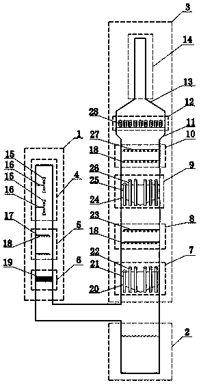
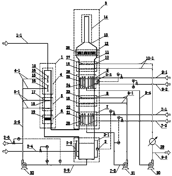
[0089] A flue gas dust removal and desulfurization tower, comprising a pretreatment unit 1, an advanced treatment unit 3, and a liquid holding tank area at the bottom of the tower. The pretreatment unit 1 and the advanced treatment unit 3 are connected through a flue gas pipeline, and the three constitute a "single-shaped" structure . The pretreatment unit 1 includes the quench spray area 4, the primary spray area 5, and the Venturi grid washing area 6 from top to bottom; the advanced treatment unit 3 includes the middle liquid holding tank area 7, and the secondary spray area from bottom to top. Shower area 8, upper liquid holding tank area 9, three-stage spray area 10, demister area 12, and flue gas discharge area 14.

[0090] The top of the quench spray area 4 is connected to the flue gas pipeline 1-1. The quench spray area 4 is provided with two layers of spray pipelines I 16. The distance between the spray pipelines I 16 is 2m, and the spray pipeline I 16 is provided with a ...


PUM

PropertyMeasurementUnit
particle diameteraaaaaaaaaa
heightaaaaaaaaaa

Abstract

The invention discloses a flue gas dedusting and desulfurizing tower and a flue gas dedusting and desulfurizing method. The flue gas dusting and desulfurizing tower comprises a pretreatment unit, an advanced treatment unit and a tower bottom liquid tank area, and the pretreatment unit is communicated with the advanced treatment unit by a flue gas pipeline. The pretreatment unit sequentially comprises a quenching and spraying area, a first-stage spraying area and a Venturi grating washing area from top to bottom; and the advanced treatment unit sequentially comprises a middle liquid tank area,a second-stage spraying area, an upper liquid tank area, a third-stage spraying area, a demisting area and a flue gas discharging area from bottom to top. The white smoke phenomenon of wet desulfurization is eliminated, so the white smoke phenomenon of a smoke discharging opening is significantly reduced; and the triple functions of flue gas dedusting, desulfurizing and advanced demisting are achieved in the tower, and all functional areas cooperate with each other and promote each other, so the occupied area of the tower is greatly reduced, and the cost for construction and reconstruction ofthe tower is significantly reduced.

Description

Technical field [0001] The invention belongs to the field of industrial waste gas purification, and relates to a flue gas dust removal and desulfurization tower and a dust removal and desulfurization method. Background technique [0002] Boiler flue gas and flue gas discharged from factories contain sulfur dioxide and dust. Both sulfur dioxide and dust are the main components of air pollutants. Sulfur dioxide is the main cause of acid rain. Dust with a smaller particle size is one of the culprits for the formation of haze. One. [0003] Wet desulfurization has the advantages of high desulfurization rate, reliable operation of the device, and simple operation. Therefore, the existing flue gas desulfurization technologies in various countries in the world are mainly wet desulfurization. The traditional wet desulfurization technology mainly includes limestone-gypsum method, two-alkali desulfurization, sodium-alkali desulfurization, ammonia desulfurization and so on. The above-mentio...

Claims


Application Information

Patent Timeline
Patent Type & Authority Patents(China)
IPC IPC(8): B01D53/80B01D53/50B01D47/12
CPCB01D47/12B01D53/50B01D53/80B01D2258/0283
Inventor 李欣李磊刘淑鹤刘忠生韩天竹王昊辰王海波金平
Owner CHINA PETROLEUM & CHEM CORP
Why Eureka
Try Eureka