Fcc counter-current regenerator

A regenerator and countercurrent contact technology, which is applied in catalyst regeneration/reactivation, chemical instruments and methods, physical/chemical process catalysts, etc., can solve problems such as hot spots, increased catalyst deactivation, and reduced combustion efficiency

Pending Publication Date: 2018-10-23
UOP LLC
View PDF11 Cites 0 Cited by
  • Summary
  • Abstract
  • Description
  • Claims
  • Application Information

AI Technical Summary

Problems solved by technology

Back mixing results in increased residence time and non-uniform burn rates, which create hot spots, increase catalyst

Method used


Image

  • Fcc counter-current regenerator
  • Fcc counter-current regenerator
  • Fcc counter-current regenerator

Examples


Embodiment 1

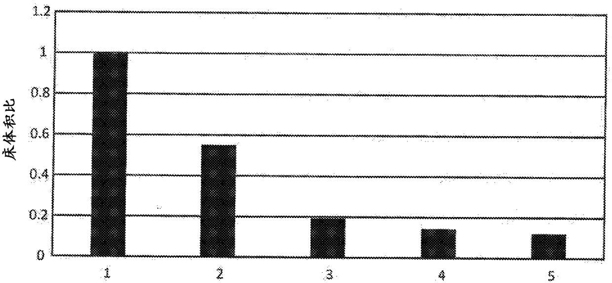
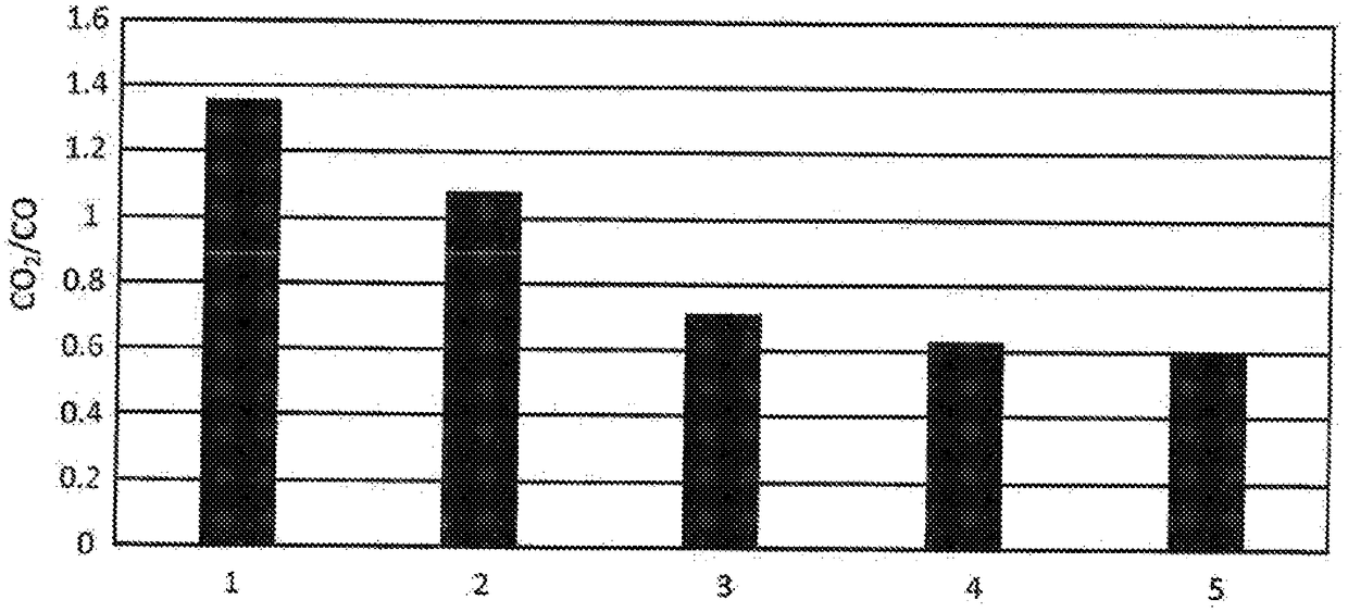
[0070] We performed kinetic simulations comparing bubbling bed regenerators and two to five stage countercurrent regeneration. The bubbling bed is modeled more rigorously than the single-stage continuous stirred tank reactor model in a manner that can be used for computational fluid dynamics simulations. Each stage of the countercurrent regenerator was modeled as a continuous stirred tank reactor without catalyst dilute phase. All simulation cases used the same total catalyst weight, the same total air weight flow rate, the same coke weight concentration on the coked catalyst and the same target coke concentration on the regenerated catalyst. Therefore, each regenerator simulated must burn the same total mass of coke. For each countercurrent regenerator, the same total mass of coke must be burned throughout the regenerator, but the amount of coke burned in each stage of the countercurrent regenerator is determined by the kinetics that occur in equal volumes at each stage.

...

Embodiment 2

[0074] We simulated a countercurrent regenerator with five-stage countercurrent contacting under the same conditions as in Example 1.

[0075] Figure 5 is a graph of the weight percent coke concentration on the catalyst on the left axis and the volume percent oxygen concentration in the gas on the right axis for each countercurrent regeneration stage. The first stage where the coked catalyst was first sent to the regenerator had the highest coke concentration and the lowest coke concentration in the fifth stage, which was the final stage of this study. Oxygen is highest in the final stage of its first distribution and lowest in the first stage. The counter-current arrangement allows the greatest concentration of oxygen to be present at the stage where the coke concentration is lowest and most difficult to burn, and the least oxygen concentration to exist where the coke concentration is highest and most flammable. Therefore, high oxygen concentration or high coke concentrati...


PUM


Abstract

A counter-current catalyst regenerator with at least two stages of counter-current contact is proposed. Each stage may comprise a permeable barrier that allows upward passage of oxygen-containing gasand downward passage of coked catalyst into each stage, but inhibits upward movement of catalyst to mitigate back mixing and true counter-current contact and efficient combustion of coke from catalyst.

Description

[0001] priority statement [0002] This application claims priority to US Application No. 62 / 316487, filed March 31, 2016, the contents of which are incorporated herein by reference in their entirety. field of invention [0003] The subject matter field relates to catalyst regeneration in fluid catalytic cracking units, and more specifically to countercurrent catalyst regenerators. Background technique [0004] Fluid catalytic cracking (FCC) is a hydrocarbon conversion process accomplished by contacting hydrocarbons with a catalyst consisting of finely divided particulate material in a fluidized reaction zone. In contrast to hydrocracking, the reactions in catalytic cracking take place without significant addition or consumption of hydrogen. As the cracking reaction proceeds, large amounts of high carbonaceous material known as coke are deposited on the catalyst. The high temperature regeneration operation in the regeneration zone burns coke from the catalyst. Coke-contai...

Claims


Application Information

Patent Timeline
IPC IPC(8): B01J38/04B01J8/18
CPCB01J38/04B01J38/34B01J29/90B01J8/26B01J8/34B01J8/0025B01J8/003B01J8/0065B01J8/008B01J2208/00752B01J2208/00769B01J2208/00902B01J2208/00938B01J2208/00991B01J8/0055C10G11/182C10G2300/207C10G2300/708B01J8/28B01J38/26B01J38/30
Inventor Z·费L·M·沃斯什拉格B·W·赫德里克
Owner UOP LLC
Why Eureka
Try Eureka