Fcc counter-current regenerator with regenerator riser

A regenerator and riser technology, applied in the field of countercurrent catalyst regenerators, can solve the problems of large size and high construction cost of FCC regenerators

Pending Publication Date: 2019-09-13
UOP LLC
View PDF9 Cites 0 Cited by
  • Summary
  • Abstract
  • Description
  • Claims
  • Application Information

AI Technical Summary

Problems solved by technology

[0011] FCC regenerators are large in size and expensive to construct

Method used


Image

  • Fcc counter-current regenerator with regenerator riser
  • Fcc counter-current regenerator with regenerator riser

Examples


Embodiment Construction

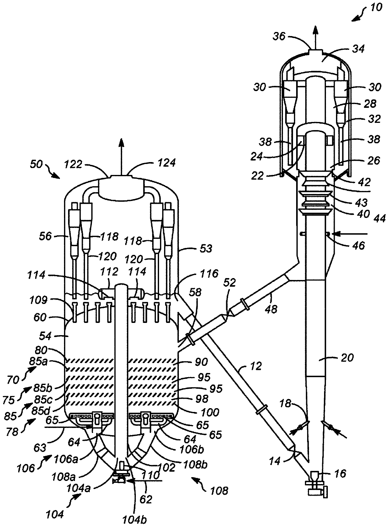
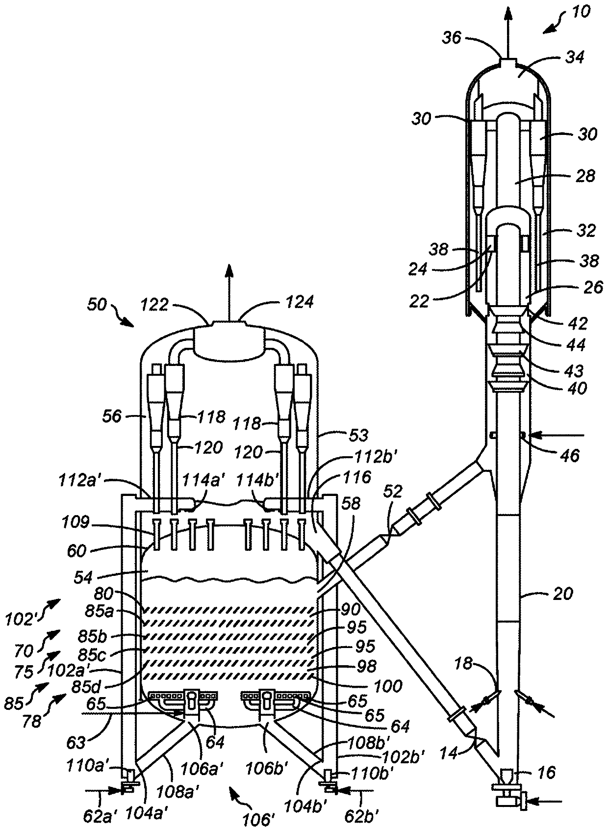
[0016] A new regenerator is proposed where the catalyst and gas streams are countercurrent to each other in multiple stages and are provided with either an internal regenerator riser or an external regenerator riser to facilitate catalyst delivery. A permeable barrier above each stage facilitates countercurrent flow of catalyst by alleviating catalyst back mixing. The permeable barrier may also have a structure that promotes efficient mixing between the catalyst and combustion gases. Each stage may also include open volume sections between adjacent permeable barriers. From one stage the catalyst flows down through the lower permeable barrier and from the stage the oxygen-containing gas flows up through the upper permeable barrier. One or more stages can be assembled in a regenerator vessel to approximate true countercurrent flow conditions. In addition, the regenerator riser can be used as the final polishing stage for catalyst regeneration after countercurrent regeneration ...


PUM


Abstract

A counter-current catalyst regenerator with at least two stages of counter-current contact along with a regenerator riser is proposed. Each stage may comprise a permeable barrier that allows upward passage of oxygen-containing gas and downward passage of coked catalyst into each stage, but inhibits upward movement of catalyst to mitigate back mixing and true counter-current contact and efficient combustion of coke from catalyst. The regenerator riser may provide a passage to transport the catalyst and may serve as a secondary stage for coke combustion to provide the regenerated catalyst.

Description

[0001] priority statement [0002] This application claims priority to U.S. Patent Application No. 62 / 439,346, filed December 27, 2016, the contents of which are hereby incorporated by reference in their entirety. technical field [0003] The field of the subject matter relates to catalyst regeneration in fluid catalytic cracking units, and more particularly to countercurrent catalyst regenerators with regenerator risers. Background technique [0004] Fluid catalytic cracking (FCC) is a hydrocarbon conversion process accomplished by contacting hydrocarbons in a fluidized reaction zone with a catalyst. As the cracking reaction proceeds, large amounts of high carbonaceous material called coke are deposited on the catalyst. The high temperature regeneration operation in the regeneration zone burns coke from the catalyst. Coke-containing catalyst (referred to herein as coked catalyst) is continuously removed from the reactor and replaced with substantially coke-free catalyst f...

Claims


Application Information

Patent Timeline
IPC IPC(8): B01J38/34B01J8/44
CPCB01J38/34B01J38/20B01J29/90B01J8/1872B01J38/70B01J38/02F27B15/09B01J8/28C10G11/182B01J2208/00938F23C13/08
Inventor 列夫·达维多夫迈克尔·S·桑达茨保罗·帕尔马斯费志浩马修·李普曼
Owner UOP LLC
Why Eureka
Try Eureka