Unmanned aerial system based thermal imaging and aggregation systems and methods

A technology of infrared imaging and aggregation server, applied in the field of thermal imaging of UAV system

Pending Publication Date: 2018-10-23
FLIR SYST INC
View PDF1 Cites 4 Cited by
  • Summary
  • Abstract
  • Description
  • Claims
  • Application Information

AI Technical Summary

Problems solved by technology

As the use of flight-based infrared surveillance systems increases, comes the need to improve the reliability and accuracy of such systems while adhering to regulatory restrictions on their use

Method used


Image

  • Unmanned aerial system based thermal imaging and aggregation systems and methods
  • Unmanned aerial system based thermal imaging and aggregation systems and methods
  • Unmanned aerial system based thermal imaging and aggregation systems and methods

Examples


Embodiment Construction

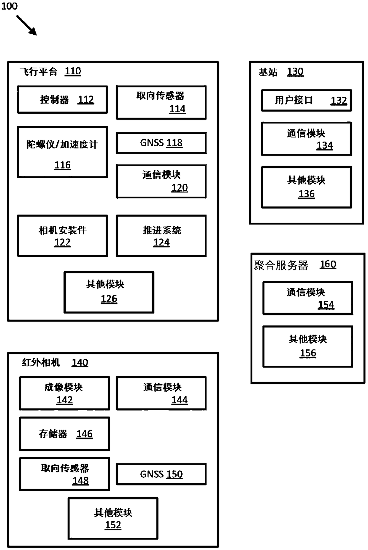
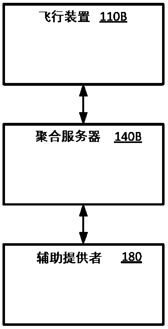
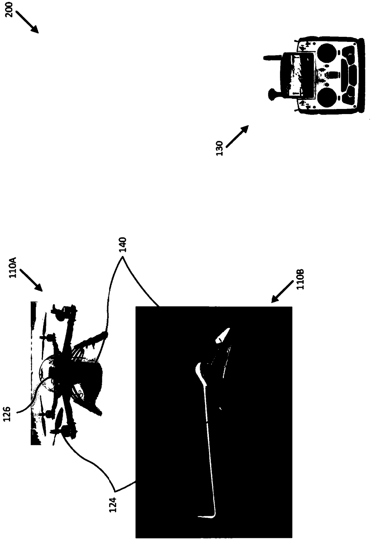
[0032] Provide flight-based infrared imaging systems and related technologies, particularly UAS-based thermal imaging systems, to improve the surveillance capabilities of such systems relative to conventional infrared surveillance systems. In some embodiments, the infrared imaging system can be configured to compensate for various environmental influences (e.g., position and / or strength of the sun, atmospheric effects) to provide high resolution and accuracy of radiance of targets imaged by the infrared imaging system Measurement results, as described herein. In other embodiments, the infrared imaging system may be configured to calculate and report radiometric measurements for each pixel of the thermal image, as described herein. Additionally, as described herein, data from infrared imaging systems can be used to create panoramic or three-dimensional (3D) thermal representations. In other embodiments, the infrared imaging system may be configured to monitor regulatory restri...


PUM


Abstract

Flight based infrared imaging systems and related techniques, and in particular UAS based thermal imaging systems, are provided to improve the monitoring capabilities of such systems over conventionalinfrared monitoring systems. An infrared imaging system is configured to compensate for various environmental effects (e.g., position and / or strength of the sun, atmospheric effects) to provide highresolution and accuracy radiometric measurements of targets imaged by the infrared imaging system. An infrared imaging system is alternatively configured to monitor and determine environmental conditions, modify data received from infrared imaging systems and other systems, modify flight paths and other commands, and / or create a representation of the environment.

Description

[0001] Jeffrey D. Frank, Thomas J. Scanlon, Theodore R. Hoelter, Nicholas Austin A. Richards, Michael Kent, Julie R. Moreira, Pierre M. Boulanger, Raymond Valdes, and Jonathan Li [0002] Cross References to Related Applications [0003] This application claims priority to and benefit of U.S. Provisional Patent Application No. 62 / 265,413, filed December 9, 2015, entitled "AIRBORNE INSPECTION SYSTEMS ANDMETHODS," the entire contents of which are hereby incorporated by reference. [0004] This application claims priority to and benefit of U.S. Provisional Patent Application No. 62 / 265,415, filed December 9, 2015, entitled "AIRBORNE RADIOMETRIC CAMERASYSTEMS AND METHODS," which is hereby incorporated by reference in its entirety. [0005] This application claims priority to and benefit of U.S. Provisional Patent Application No. 62 / 265,416, filed December 9, 2015, entitled "POSITION ENABLED INFRARED CAMERACONTROL SYSTEMS AND METHODS," which is hereby incorporated by reference in i...

Claims


Application Information

Patent Timeline
Patent Type & Authority Applications(China)
IPC IPC(8): G01J5/26G01J5/06H02S50/00G01J5/10G01J5/03
CPCH04W4/046G01J5/0265G01J5/061H02S50/00G01J2005/0077G01J5/007Y02E10/50G01J5/804G01J5/064G01J5/80H04N23/71H04N23/76B64U2101/30B64U2201/10B64U2201/20B64C39/024G01J5/06H02J4/00H04N5/33G03B15/006G08G5/0091H02S50/15G01J5/00H04N7/185H04W84/18
Inventor J·D·弗兰克T·J·斯坎伦T·R·赫尔特N·霍根斯特恩A·A·理查兹迈克尔·肯特J·R·莫雷拉P·M·布朗热R·瓦尔德斯J·李
Owner FLIR SYST INC
Why Eureka
Try Eureka