Novel speed-limiting deceleration strip

A deceleration belt and speed limit technology, which is applied in the field of new speed deceleration belts, can solve problems such as damage to the suspension of the car's shock absorption system, affect driving, and ride comfort, and achieve the effect of avoiding the car from being bumped and having a good deceleration effect

Inactive Publication Date: 2018-10-26
内蒙古达尔科技有限公司
View PDF7 Cites 4 Cited by
  • Summary
  • Abstract
  • Description
  • Claims
  • Application Information

AI Technical Summary

Problems solved by technology

[0002] The speed bump is a traffic facility installed on the road to slow down the passing vehicles. It is generally strip-shaped or dot-shaped. The material is mainly rubber or metal. It is generally yellow and black to attract visual attention; the speed bump is used The road surface is slightly arched to achieve the purpose of vehicle deceleration. It is generally set at highway crossings, industrial and mining enterprises, schools, residential quarter entrances, etc., where vehicles need to slow down and road sections that are prone to traffic accidents. New traffic special safety settings for driving speed; speed bumps greatly reduce the occurrence of accidents at major traffic crossings, and are new special facilities for traffic safety; cars are safe while driving and serve the purpose of buffering and decelerating, improving the safety of traffic crossings However, there is a common problem with the current deceleration. Even if the car has slowed down enough, it will still bump the driver. This will cause certain damage to the car's shock absorption system and suspension in the long run. A headache, which greatly affects the comfort of driving and riding

Method used


Image

  • Novel speed-limiting deceleration strip
  • Novel speed-limiting deceleration strip
  • Novel speed-limiting deceleration strip

Examples


Embodiment Construction

[0022] The technical solutions of the present invention are described in detail below with reference to example embodiments; however, example embodiments can be implemented in various forms and should not be construed as being limited to the embodiments set forth herein; on the contrary, these embodiments are provided to make the present invention more comprehensive and complete, and fully convey the concept of the example embodiments to those skilled in the art.

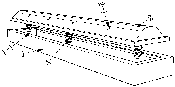
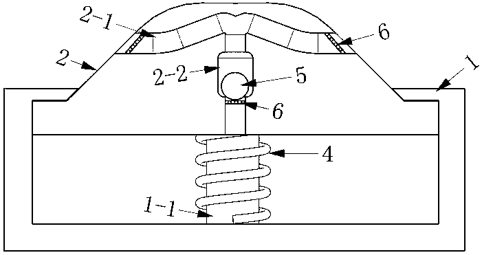
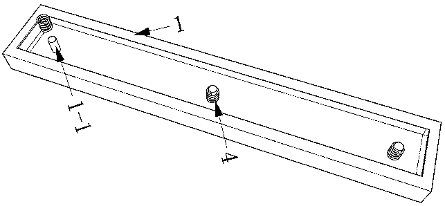
[0023] Such as figure 1 , figure 2 As shown, a novel speed-limiting deceleration belt includes a cylinder cavity 1, a deceleration belt 2, a compression spring 4, and a floating ball 5; it is characterized in that the inner bottom surface of the cylinder cavity 1 is provided with a limit post 1-1; A compression spring 4 is set on the limit post 1-1; the deceleration belt 2 is installed together with the cylinder cavity 1; the outer leakage surface of the deceleration belt 2 and the lower bottom surface of the dece...


PUM


Abstract

The invention discloses a novel speed-limiting deceleration strip which comprises an air cylinder cavity, a deceleration strip body, compression springs and floating balls. The novel speed-limiting deceleration strip is characterized in that limiting columns are arranged on the inner bottom face of the air cylinder cavity and sleeved with the compression springs; the deceleration strip body and the air cylinder cavity are mounted together in a matched mode; exhaust holes are formed in the exposed surface and the lower bottom face of the deceleration strip body in a penetrating mode, and the lower bottom faces, close to the deceleration strip body, of the exhaust holes are provided with floating ball buffer areas; the diameter of the floating ball buffer areas is larger than that of other parts of the exhaust holes; the floating balls are mounted in the floating ball buffer areas of the exhaust holes; and cylindrical grooves used for mounting the limiting columns in a matched mode are further formed in the lower bottom face of the deceleration strip body. The deceleration strip takes the deceleration effect on vehicles with the high vehicle speed and does not take the effect on vehicles with the low vehicle speed; in addition, the deceleration strip is simple in structure and not prone to damage; and the vehicles can be limited to travel within the specified speed, and under thepremise that safety is guaranteed, jolt to the vehicles is avoided.

Description

technical field [0001] The invention designs the field of traffic equipment, and in particular relates to a novel speed-limiting speed bump. Background technique [0002] The speed bump is a traffic facility installed on the road to slow down the passing vehicles. It is generally strip-shaped or dot-shaped. The material is mainly rubber or metal. It is generally yellow and black to attract visual attention; the speed bump is used The road surface is slightly arched to achieve the purpose of vehicle deceleration. It is generally set at highway crossings, industrial and mining enterprises, schools, residential quarter entrances, etc., where vehicles need to slow down and road sections that are prone to traffic accidents. New traffic special safety settings for driving speed; speed bumps greatly reduce the occurrence of accidents at major traffic crossings, and are new special facilities for traffic safety; cars are safe while driving and serve the purpose of buffering and dece...

Claims


Application Information

Patent Timeline
Patent Type & Authority Applications(China)
IPC IPC(8): E01F9/529
CPCE01F9/529
Inventor 侯建伟张亚伟郭磊张世成魏瑞霞苏宇
Owner 内蒙古达尔科技有限公司
Why Eureka
Try Eureka