Current collector, positive electrode plate fabricated by employing same and battery cell

A current collector and tab technology, which is applied in the field of positive pole pieces and batteries, can solve the problems of poor electrical conductivity of polymer collectors, failure to meet the needs of battery use, poor adhesion of active materials, etc., to reduce the probability of burrs and short circuits , Improve the conductivity and uniformity of conductivity, and improve the effect of adhesion performance

Pending Publication Date: 2018-11-02
ETRUST POWER ETP GRP LTD
View PDF8 Cites 12 Cited by
  • Summary
  • Abstract
  • Description
  • Claims
  • Application Information

AI Technical Summary

Problems solved by technology

[0003] Under some abuse conditions, such as extrusion, acupuncture, impact, etc., the positive electrode sheet will be broken due to external force. Since the positive electrode sheet contains two parts, the current collector and the positive electrode active material, the ductility of the two is different. , so the current collector is exposed from the positive pole piece, and then pierces the separator and short-circuits with the negative electrode, which will cause the battery to fail
Most of the existing current collectors are aluminum foil current collectors, and some ...

Method used


Image

  • Current collector, positive electrode plate fabricated by employing same and battery cell
  • Current collector, positive electrode plate fabricated by employing same and battery cell
  • Current collector, positive electrode plate fabricated by employing same and battery cell

Examples


Embodiment 1

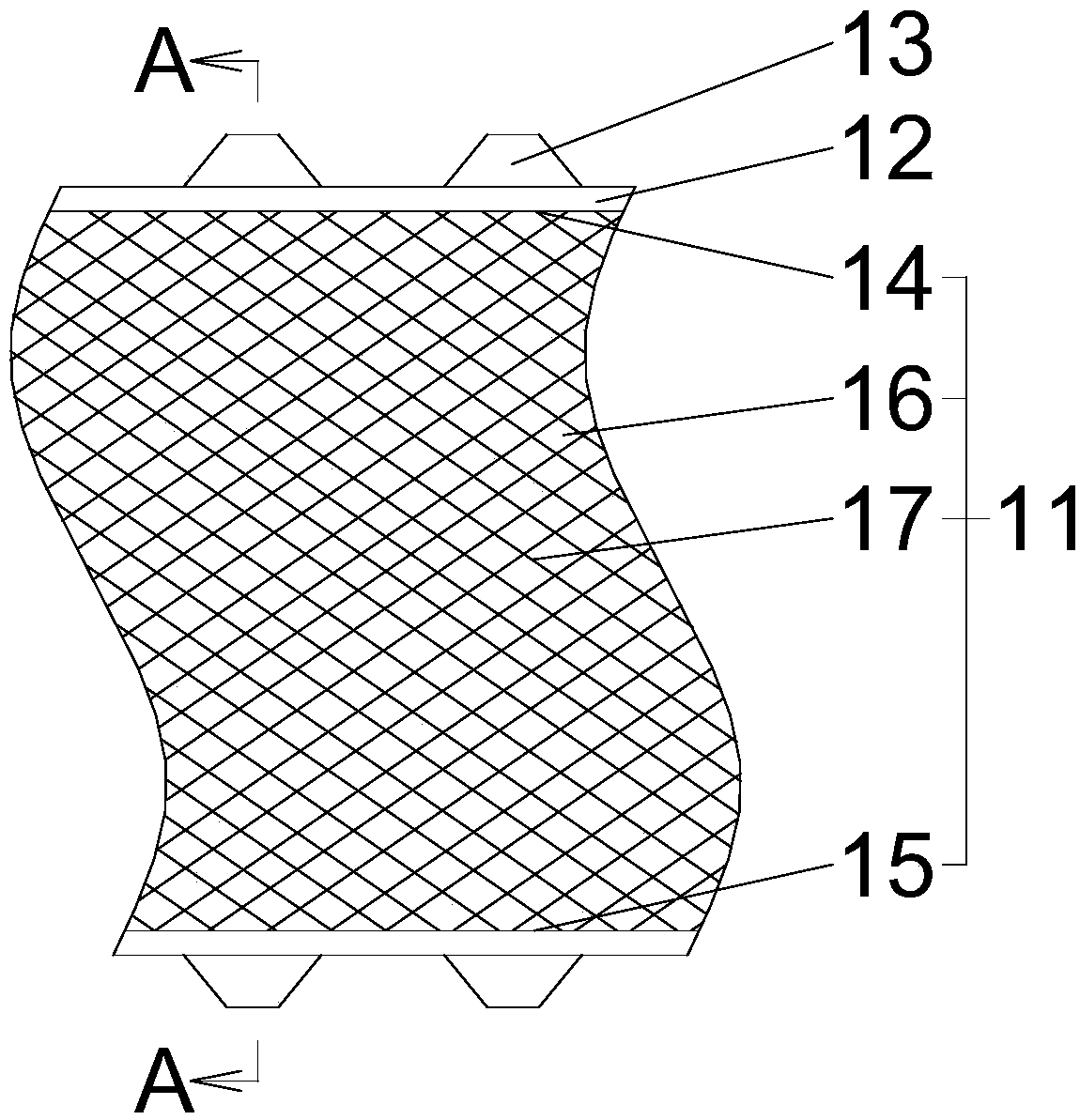
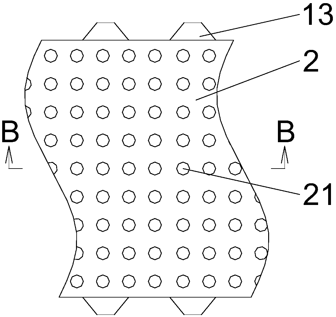
[0023] A current collector, such as attached Figure 1~4 As shown, a conductive mesh 1 and a polymer porous membrane 2 are included.

[0024] as attached figure 1 , 2 As shown, the conductive mesh 1 includes a grid area 11, a transition area 12, and a tab area 13. The transition area 12 is respectively located on a group of opposite sides 14, 15 of the grid area 11, and the transition area 12 is along the sides 14, 15, respectively. 15 continuous strips, the outer side of transition zone 12, that is, the side where transition zone 12 connects with grid zone 11, its opposite side, is connected with tab region 13, grid zone 11, transition zone 12, pole The thickness of the ear region 13 increases successively. The material of the conductive mesh 1 is one of aluminum, nickel, graphite, etc., and it is made by roll forming. The shape of the mesh 16 on the grid area 11 is rhombus, square, etc.

[0025] as attached image 3 , 4 As shown, the upper and lower surfaces of the con...

Embodiment 2

[0034] It is basically the same as Example 1, the difference is that the polymer porous membrane and the surface of the conductive network are adhered by bonding. At this time, the polymer porous membrane is a double-layer film formed by a base layer and an adhesive layer, and the material of the base layer is PET, One of PP, PE, etc., the material of the adhesive layer is one of HMA, SIS, etc., and the polymer porous film is bonded to the surface of the conductive mesh through the adhesive layer.

[0035] The holes on the polymer porous membrane on the upper and lower surfaces of the conductive mesh are opposite up and down, that is, a certain hole on the polymer porous membrane on the upper surface of the conductive mesh, the connection line on the grid area, and the polymer on the lower surface of the conductive mesh. A certain hole on the porous membrane is connected to form an electrical connection through the conductive coating. A certain hole on the polymer porous membr...


PUM


Abstract

The invention discloses a current collector. The current collector comprises a conductive network and polymer porous films, wherein transition regions of the conductive network are respectively arranged at a group of opposite sides of a grid region and are continued along the side edges, tab regions are arranged at an outer sides of the transition regions and are connected, the polymer porous films are respectively attached onto an upper surface and a lower surface of the conductive network, the polymer porous films cover the grid regions and transition strip regions, and holes of the polymerporous films are corresponding to connection lines on the grid regions. The invention simultaneously discloses a positive electrode plate fabricated by employing the same. A conductive coating layer and a positive electrode material layer are sequentially coated on a surface of an outer side of the current collector and at least correspondingly cover the polymer porous films, the holes of the polymer porous films are filled with the conductive coating layer, and the conductive coating layer reaches the connection lines of the grid regions. The current collector has the advantages that the structural strength, the overcurrent capability and the conductivity of the current collector and the adhesivity of the positive electrode material are improved, and the burr short-circuit probability easy to generate on the current collector on the positive electrode plate during abusing is reduced.

Description

technical field [0001] The invention relates to a lithium-ion battery, in particular to a current collector in the lithium-ion battery, and a positive pole piece and an electric core prepared by using the current collector. Background technique [0002] Lithium-ion batteries are widely used in daily life, especially in consumer and electric vehicle fields, and the safety performance of lithium-ion batteries has also attracted more people's attention. [0003] Under some abuse conditions, such as extrusion, acupuncture, impact, etc., the positive electrode sheet will be broken due to external force. Since the positive electrode sheet contains two parts, the current collector and the positive electrode active material, the ductility of the two is different. , so the current collector is exposed from the positive pole piece, and then pierces the separator and short-circuits with the negative electrode, which will cause the cell to fail. Most of the existing current collectors ...

Claims


Application Information

Patent Timeline
IPC IPC(8): H01M4/66H01M4/74H01M4/13H01M10/058
CPCH01M4/13H01M4/667H01M4/668H01M4/742H01M10/058Y02E60/10Y02P70/50
Inventor 周立健侯小贺程君张子轮
Owner ETRUST POWER ETP GRP LTD
Why Eureka
Try Eureka