Camera module and electronic equipment

A camera component and camera technology, applied in branch equipment, television, telephone communication, etc., can solve the problems of small shooting angle, poor shooting effect, and inability to satisfy users, and achieve good shooting effect.

Active Publication Date: 2018-11-02
GUANGDONG OPPO MOBILE TELECOMM CORP LTD
View PDF4 Cites 4 Cited by
  • Summary
  • Abstract
  • Description
  • Claims
  • Application Information

AI Technical Summary

Problems solved by technology

The shooting angle of the traditional single camera mode or dual camera mode is small, resulting in poor shooting effect and unable to meet the needs of users

Method used


Image

  • Camera module and electronic equipment
  • Camera module and electronic equipment
  • Camera module and electronic equipment

Examples


Embodiment approach 1

[0031] Implementation mode one: if Figure 5As shown, the first light incident surface 111 is disposed toward the second light incident surface 121 . The third light incident surface 131 is disposed toward the second light incident surface 121 . That is, the direction of the normal vector of the first light incident surface 111 is located between the positive direction of the Z axis and the positive direction of the X axis. At this time, when the object is photographed by the second camera 12, the second camera 12 can only photograph the S1 area of ​​the object. The area outside the S1 area is the shooting blind area of ​​the second camera 12 . When the first camera 11 and the third camera 13 cooperate with the second camera 12 to take pictures, part of the shooting blind area of ​​the second camera 12 is taken by the first camera 11 and the third camera 13 . Therefore, when the first camera 11 and the third camera 13 cooperate with the second camera 12 to shoot an object, ...

Embodiment approach 2

[0032] Embodiment 2 is different from Embodiment 1 in that: if Figure 6 As shown, the first light incident surface 111 is disposed away from the second light incident surface 121 . The third light incident surface 131 is disposed opposite to the second light incident surface 121 . That is, the direction of the normal vector of the first light incident surface 111 is located between the positive direction of the Z axis and the negative direction of the X axis. At this time, when the object is photographed by the second camera 12, the second camera 12 can only photograph the S2 area of ​​the object. The area outside the S2 area is the shooting blind area of ​​the second camera 12 . When the first camera 11 and the third camera 13 cooperate with the second camera 12 to take pictures, part of the shooting blind area of ​​the second camera 12 is taken by the first camera 11 and the third camera 13 . Therefore, when the first camera 11 and the third camera 13 cooperate with the ...


PUM


Abstract

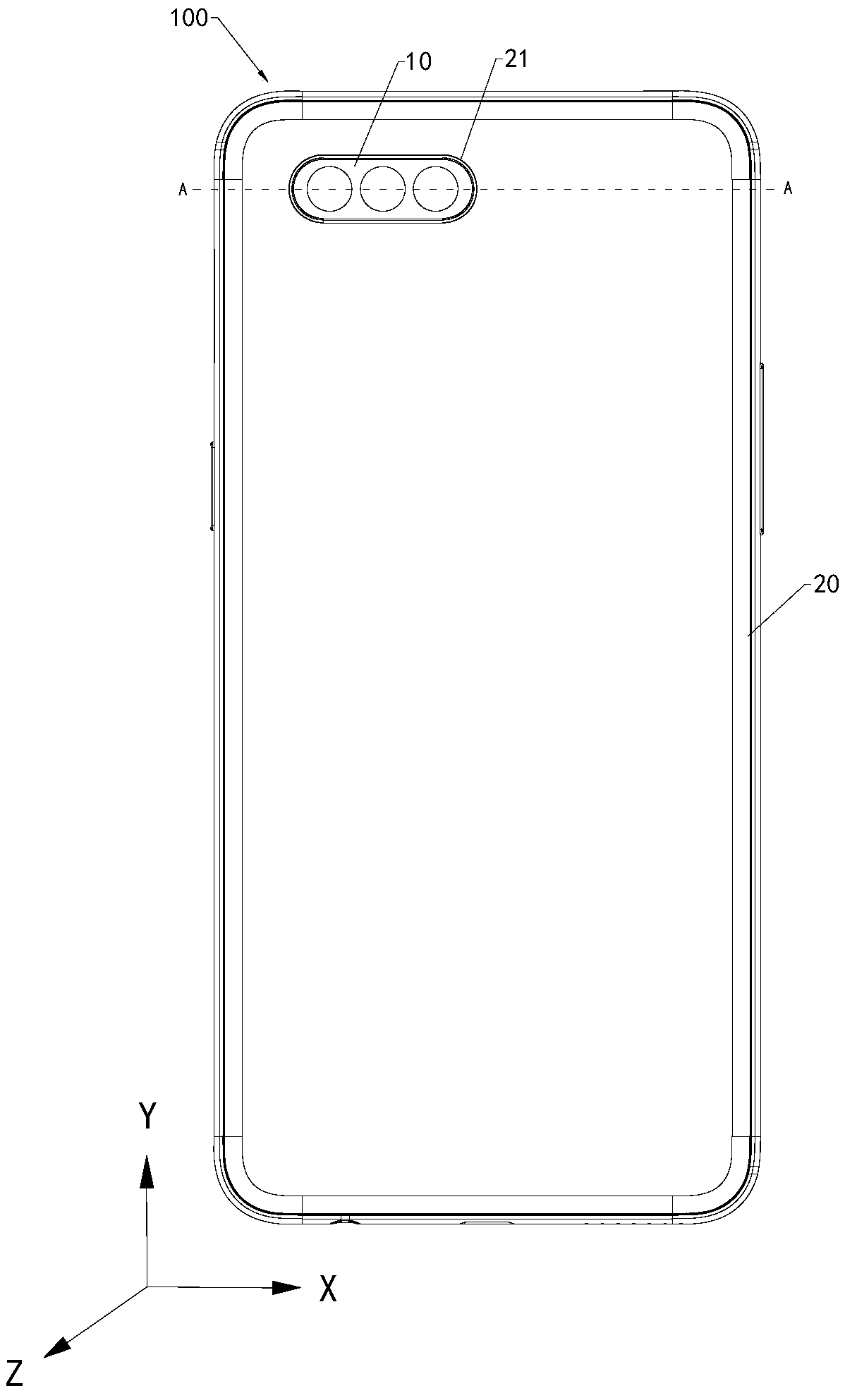
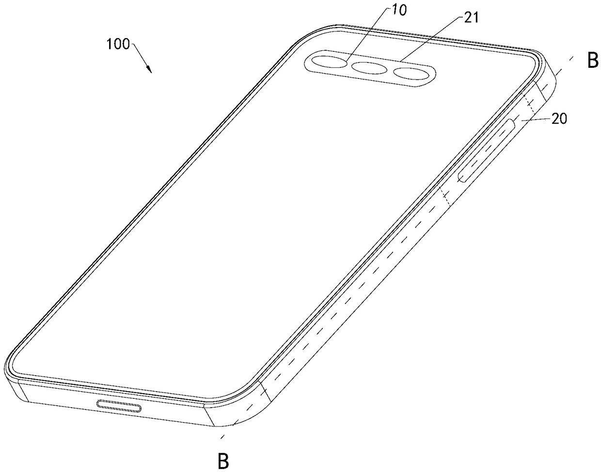
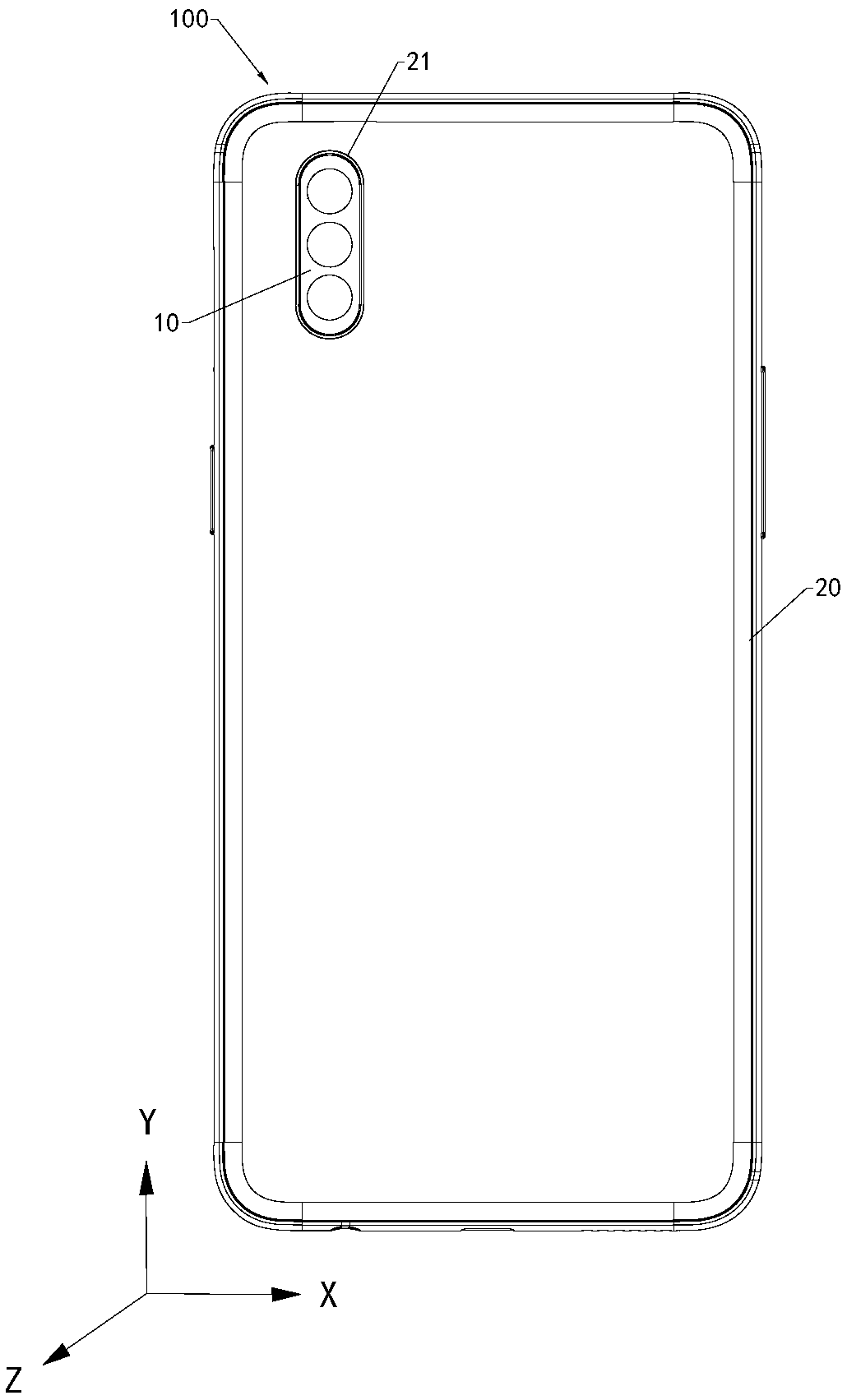
The application discloses a camera module. The camera module comprises a first camera, a second camera, and a third camera; the first camera, the second camera and the third camera are arranged on thesame direction at intervals, the second camera is located between the first camera and the second camera, the first camera comprises a first incident surface, the second camera comprises a second incident surface, and the third camera comprises a third incident surface; a first preset angle is formed between the first incident surface and the second incident surface, a second preset angle is formed between the third incident surface and the second incident surface, the first preset angle is between 90-180 DEG, and the second preset angle is between 90-180 DEG. The above camera module is excellent in camera effect; when the camera module is applied to the electronic equipment, the electronic equipment has excellent camera effect.

Description

technical field [0001] The present application relates to the technical field of electronic equipment, in particular to a camera component and electronic equipment. Background technique [0002] With the development of electronic device technology, more and more electronic devices are integrated with cameras. The traditional single-camera mode or dual-camera mode has a small shooting angle, which leads to poor shooting effects and cannot meet the needs of users. Contents of the invention [0003] The present application provides a camera component and electronic equipment with better shooting effect. [0004] An embodiment of the present application provides a camera assembly. The camera assembly includes: a first camera, a second camera and a third camera, the first camera, the second camera and the third camera are arranged at intervals in the same direction, and the second camera is located at the Between the first camera and the third camera, the first camera includ...

Claims


Application Information

Patent Timeline
Patent Type & Authority Applications(China)
IPC IPC(8): H04N5/225
CPCH04N23/45H04N23/57H04M1/0264H04N25/41H04N23/90H04N23/54H04N23/695
Inventor 卢建强
Owner GUANGDONG OPPO MOBILE TELECOMM CORP LTD
Why Eureka
Try Eureka