Nursing stretcher bed for thoracic surgery department

A stretcher bed, thoracic surgery technology, applied in stretchers, vehicle rescue, medical transportation and other directions, can solve the problem of not having an independent stretcher, and achieve the effect of avoiding damp discomfort, aggravating the disease, and avoiding damage

Inactive Publication Date: 2018-11-06
董建丽
View PDF9 Cites 7 Cited by
  • Summary
  • Abstract
  • Description
  • Claims
  • Application Information

AI Technical Summary

Problems solved by technology

But this hospital bed does not have the function of independent stretcher use

Method used


Image

  • Nursing stretcher bed for thoracic surgery department
  • Nursing stretcher bed for thoracic surgery department
  • Nursing stretcher bed for thoracic surgery department

Examples


specific Embodiment approach 1

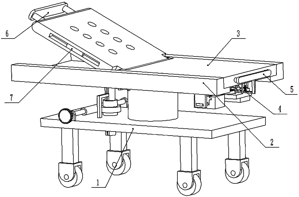
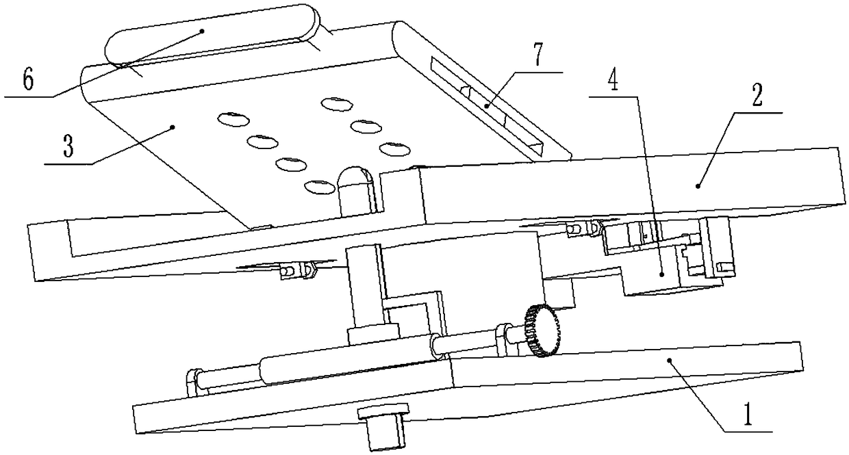
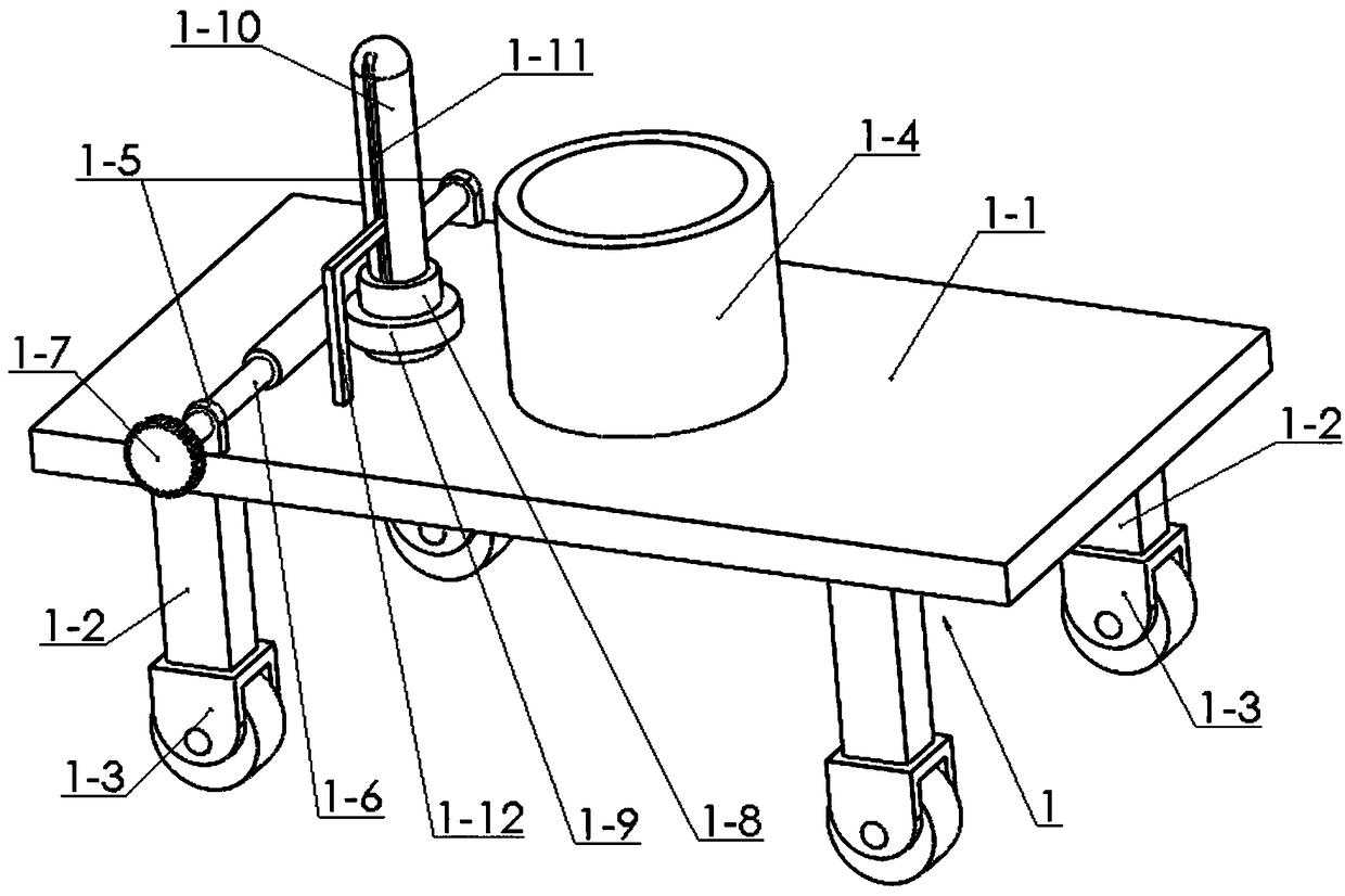
[0034] Combine below Figure 1-14Describe this embodiment, a nursing stretcher bed for thoracic surgery, including a bed body support base 1, a bed board 2, a stretcher 3, a clip assembly 4, a right handle 5, a left handle 6, and an inserting board 7. The bed The body support seat 1 includes a support plate 1-1, a support leg 1-2, a universal wheel 1-3, a support column 1-4, an internally threaded sleeve 1-8, an externally threaded rod 1-10, and a vertical chute 1- 11 and L-shaped folding rod 1-12, the four corners of the lower end of the support plate 1-1 are fixedly connected with support legs 1-2, and the lower ends of the four support legs 1-2 are all rotatably connected with universal wheels 1-3 , the support column 1-4 is fixedly connected to the upper end of the support plate 1-1, the internal thread sleeve 1-8 is rotatably connected to the support plate 1-1 through a bearing with a seat, and the external thread rod 1-10 is connected to the internal thread through a thr...

specific Embodiment approach 2

[0035] Combine below Figure 1-14 To illustrate this embodiment, the bed board 2 includes a side board 2-1, a bottom board 2-2, a placement groove 2-3, a raised edge 2-4, a vertical board 2-5 and a slot 2-6, and the bottom board 2-2 Fixedly connected between the two side plates 2-1, the front and rear ends of the base plate 2-2 are provided with placement grooves 2-3, the front and rear ends of the right end of the base plate 2-2 are fixedly connected with convex edges 2-4, the two sides The lower ends of the two raised edges 2-4 are fixedly connected with vertical plates 2-5, and the lower ends of the two vertical plates 2-5 are provided with slots 2-6; the bottom plate 2-2 is fixedly connected with the support column 1-4, The upper end of the externally threaded rod 1-10 is clearance fit on the bottom plate 2-2;

[0036] Described stretcher 3 comprises fixed frame plate 3-1, inserting screw seat 3-4, inserting screw 3-5, rotating frame plate 3-6 and screw inserting plate 3-...

specific Embodiment approach 3

[0038] Combine below Figure 1-14 To illustrate this embodiment, the clamping assembly 4 includes a chute seat 4-1, a cross-shaped chute 4-2, a cross-shaped slider 4-3, an inserting plate 4-4, a round rod 4-5, a tensile Spring Ⅰ4-6, hinge rod 4-7, round rod groove 4-8, square plate 4-9, left seat plate 4-10, right seat plate 4-11, slide rod 4-12, limit hole 4-13 , grooved rod 4-14 and limit assembly 4-15, a square plate 4-9 is fixedly connected between the two chute seats 4-1, and the outer ends of the two chute seats 4-1 are provided with cross-shaped Chute 4-2, two cross-shaped sliders 4-3 are slidably connected in two cross-shaped chutes 4-2 respectively, and the outer ends of the two cross-shaped sliders 4-3 are fixedly connected with a plugboard 4- 4. The upper ends of the two cross-shaped sliders 4-3 are fixedly connected with round rods 4-5, and the inner ends of the two cross-shaped sliders 4-3 are fixedly connected with tension springs I4-6. The other ends of the sp...


PUM


Abstract

The invention relates to the technical field of medical equipment, in particular to a nursing stretcher bed for the thoracic surgery department. Supporting legs are fixedly connected to four lower corners of a supporting plate, universal wheels are in rotational connection with lower ends of the four supporting legs respectively, and a supporting column is fixedly connected to the upper end of thesupporting plate. An internal threaded sleeve is rotationally connected to the supporting plate through a mounted bearing, an external threaded rod is in threaded connection in the internal threadedsleeve, and the upper end of the external threaded rod is semispherical. A stretcher can be taken down for single use to make it convenient to perform first aid on a patient. In a treatment process, when the patient needs to be transferred to another place, a right handle is pulled outwards to drive a clamping component to separate from a bed board, and nursing personnel can directly lift the stretcher without moving the patient, so that troubles in operation, time consumption, labor consumption and condition exacerbation caused by secondary injuries to the patient are avoided, work difficultyis lowered for the nursing personnel, an convenience in nursing is achieved.

Description

technical field [0001] The invention relates to the technical field of medical equipment, in particular to a nursing stretcher bed for thoracic surgery. Background technique [0002] The existing patent number is CN201520409427.7, a new type of multifunctional nursing bed, which includes the main body of the nursing bed, an infusion stand and an infusion stand mounting seat for installing the infusion stand. The baffle at the front end of the bed body is provided with a USB charging interface, a universal hose is installed on the right side of the front end of the nursing bed body, a mobile phone tablet clip is fixed at the end of the universal hose, and a horizontal The side plate of the side plate is provided with a slide rail, and the mounting seat of the infusion stand is correspondingly provided with balls that roll and cooperate with the slide rail. The lower end of the supporting legs around the main body of the nursing bed is connected with an inverted "Y" bar throu...

Claims


Application Information

Patent Timeline
Patent Type & Authority Applications(China)
IPC IPC(8): A61G1/02A61G1/04
CPCA61G1/02A61G1/04
Inventor 夏祝龙
Owner 董建丽
Why Eureka
Try Eureka