Nursing stretcher bed for thoracic surgery
A technology of stretcher bed and thoracic surgery, which is applied in stretcher, vehicle ambulance, medical transportation, etc. It can solve the problems of not using an independent stretcher, and achieve the effect of avoiding damp discomfort, aggravating the condition, and avoiding damage
- Summary
- Abstract
- Description
- Claims
- Application Information
AI Technical Summary
Problems solved by technology
Method used
Image
Examples
specific Embodiment approach 1
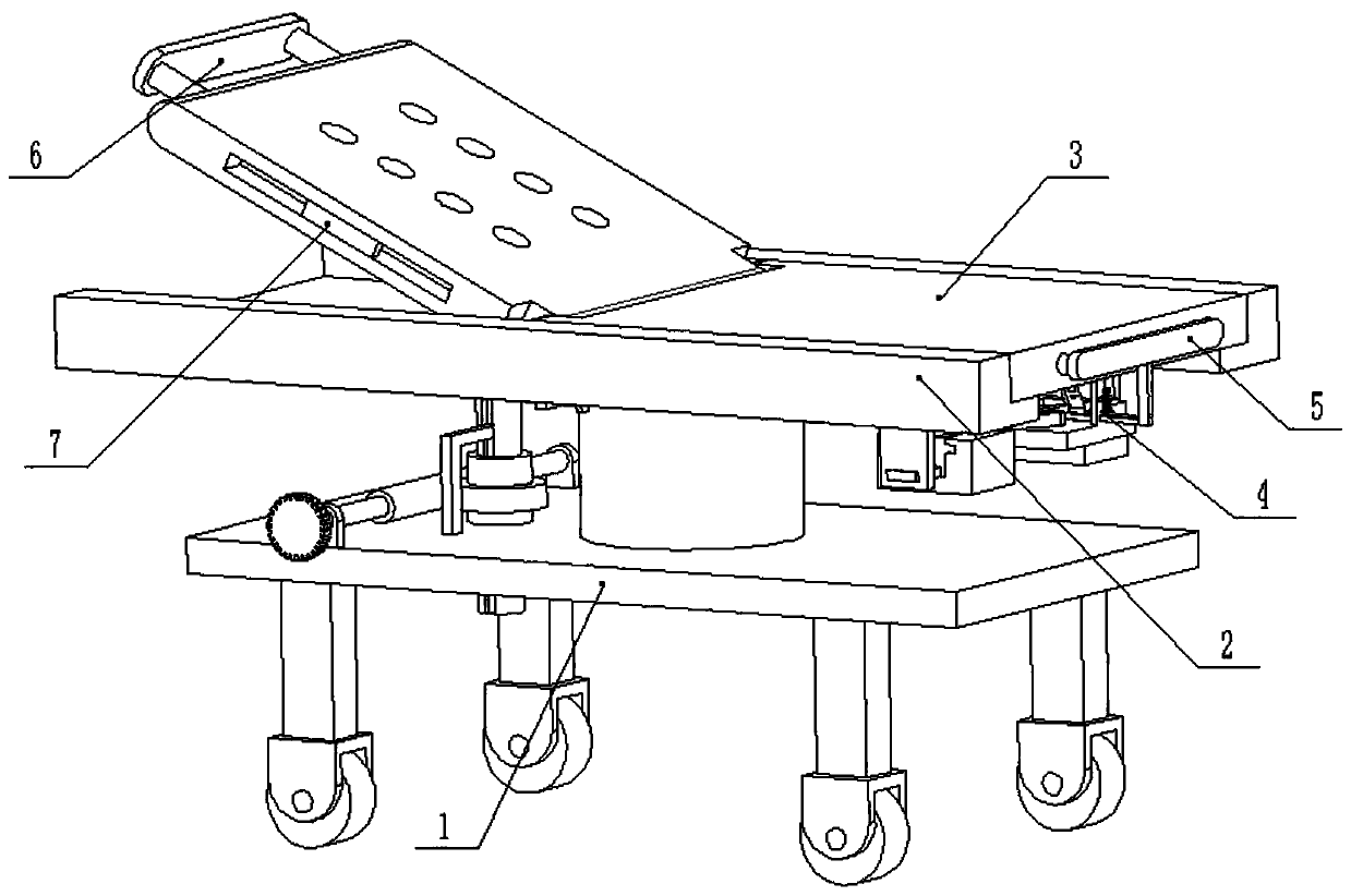
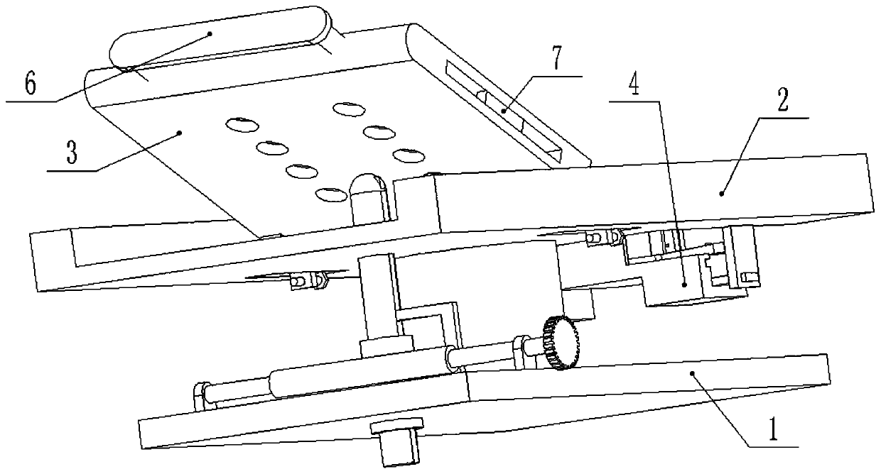
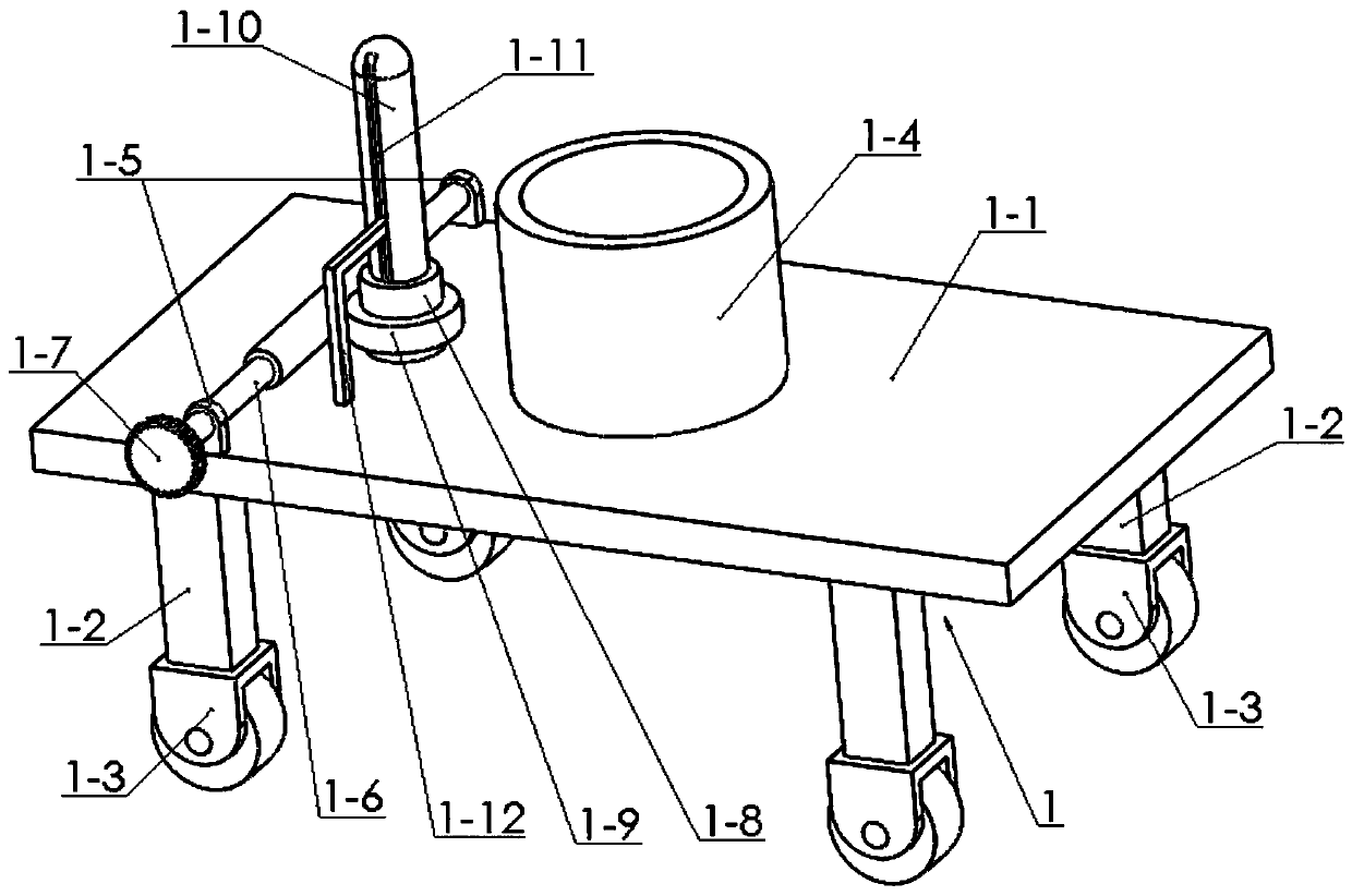
[0035] Combine below Figure 1-14Describe this embodiment, a nursing stretcher bed for thoracic surgery, including a bed body support base 1, a bed board 2, a stretcher 3, a clip assembly 4, a right handle 5, a left handle 6, and an inserting board 7. The bed The body support seat 1 includes a support plate 1-1, a support leg 1-2, a universal wheel 1-3, a support column 1-4, an internally threaded sleeve 1-8, an externally threaded rod 1-10, and a vertical chute 1- 11 and L-shaped folding rod 1-12, the four corners of the lower end of the support plate 1-1 are fixedly connected with support legs 1-2, and the lower ends of the four support legs 1-2 are all rotatably connected with universal wheels 1-3 , the support column 1-4 is fixedly connected to the upper end of the support plate 1-1, the internal thread sleeve 1-8 is rotatably connected to the support plate 1-1 through a bearing with a seat, and the external thread rod 1-10 is connected to the internal thread through a thr...
specific Embodiment approach 2
[0037] Combine below Figure 1-14 To illustrate this embodiment, the bed board 2 includes a side board 2-1, a bottom board 2-2, a placement groove 2-3, a raised edge 2-4, a vertical board 2-5 and a slot 2-6, and the bottom board 2-2 Fixedly connected between the two side plates 2-1, the front and rear ends of the base plate 2-2 are provided with placement grooves 2-3, the front and rear ends of the right end of the base plate 2-2 are fixedly connected with convex edges 2-4, the two sides The lower ends of the two raised edges 2-4 are fixedly connected with vertical plates 2-5, and the lower ends of the two vertical plates 2-5 are provided with slots 2-6; the bottom plate 2-2 is fixedly connected with the support column 1-4, The upper end of the externally threaded rod 1-10 is clearance fit on the bottom plate 2-2;
[0038] Described stretcher 3 comprises fixed frame plate 3-1, inserting screw seat 3-4, inserting screw 3-5, rotating frame plate 3-6 and screw inserting plate 3-...
specific Embodiment approach 3
[0041] Combine below Figure 1-14 To illustrate this embodiment, the clamping assembly 4 includes a chute seat 4-1, a cross-shaped chute 4-2, a cross-shaped slider 4-3, an inserting plate 4-4, a round rod 4-5, a tensile Spring Ⅰ4-6, hinge rod 4-7, round rod groove 4-8, square plate 4-9, left seat plate 4-10, right seat plate 4-11, slide rod 4-12, limit hole 4-13 , grooved rod 4-14 and limit assembly 4-15, a square plate 4-9 is fixedly connected between the two chute seats 4-1, and the outer ends of the two chute seats 4-1 are provided with cross-shaped Chute 4-2, two cross-shaped sliders 4-3 are slidably connected in two cross-shaped chutes 4-2 respectively, and the outer ends of the two cross-shaped sliders 4-3 are fixedly connected with a plugboard 4- 4. The upper ends of the two cross-shaped sliders 4-3 are fixedly connected with round rods 4-5, and the inner ends of the two cross-shaped sliders 4-3 are fixedly connected with tension springs I4-6. The other ends of the sp...
PUM
 Abstract
Description
Claims
Application Information
 - R&D
- Intellectual Property
- Life Sciences
- Materials
- Tech Scout
- Unparalleled Data Quality
- Higher Quality Content
- 60% Fewer Hallucinations
Browse by: Latest US Patents, China's latest patents, Technical Efficacy Thesaurus, Application Domain, Technology Topic, Popular Technical Reports.
© 2025 PatSnap. All rights reserved.Legal|Privacy policy|Modern Slavery Act Transparency Statement|Sitemap|About US| Contact US: help@patsnap.com


