
Method of simulating stress state of detector in soft landing test

A technology of stress state and simulation method, applied in the field of deep space exploration, can solve the problems that the soft landing verification test of the detector cannot be directly applied

Active Publication Date: 2018-11-06
BEIJING INST OF SPACECRAFT SYST ENG
View PDF11 Cites 2 Cited by
  • Summary
  • Abstract
  • Description
  • Claims
  • Application Information

AI Technical Summary

Problems solved by technology

Therefore, the conventional constant tension balance method cannot be directly applied to the soft landing verification test of the probe

Method used


Image

  • Method of simulating stress state of detector in soft landing test
  • Method of simulating stress state of detector in soft landing test
  • Method of simulating stress state of detector in soft landing test

Examples


Embodiment 1

[0026] In this embodiment, by analyzing parameters such as the quality of the detector, the acceleration range of the soft landing flight process, the actual thrust output range of the engine ground environment, and the interference force in the detector ground test, the requirements for the pulling force of the sling are determined, and the detector is assisted by the pulling force of the sling. The stress state is consistent with the real soft landing process, which can satisfy the motion simulation of the probe in the ground soft landing test. A method for simulating the stressed state of a detector in a soft landing test, comprising the following steps:

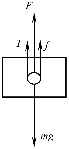
[0027] Step 1: Use the sling to provide pulling force for the detector, and obtain the engine thrust T of the detector under different force states in the soft landing test of the detector x Simulated acceleration a' with detector down 下 , upward simulated acceleration a' 上 .

[0028] It should be noted that the diff...

Embodiment 2

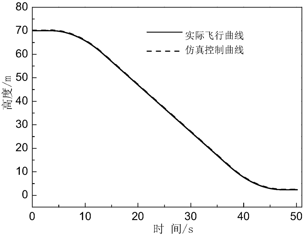
[0044] Based on the above embodiments, the method for simulating the force state of the detector in the soft landing test of the present invention will be introduced in detail below by taking the soft landing verification test of Chang'e-3 on the lunar surface as an example.

[0045] Based on the soft landing dynamics design on the lunar surface, the upward and downward motion accelerations of the probe during the soft landing process are respectively a 上 =1.1m / s 2 、a 下 =0.47m / s 2 .

[0046] Determine the thrust output range T of the engine in the ground state according to the engine thermal test run in the ground environment min =630N,T max =2710N.

[0047] According to the cross-sectional area of ​​the detector and the speed of movement, it is estimated that the maximum interference effect such as wind resistance in the test is 25N, and the dry mass of the detector is m 0 The design is 1180kg.

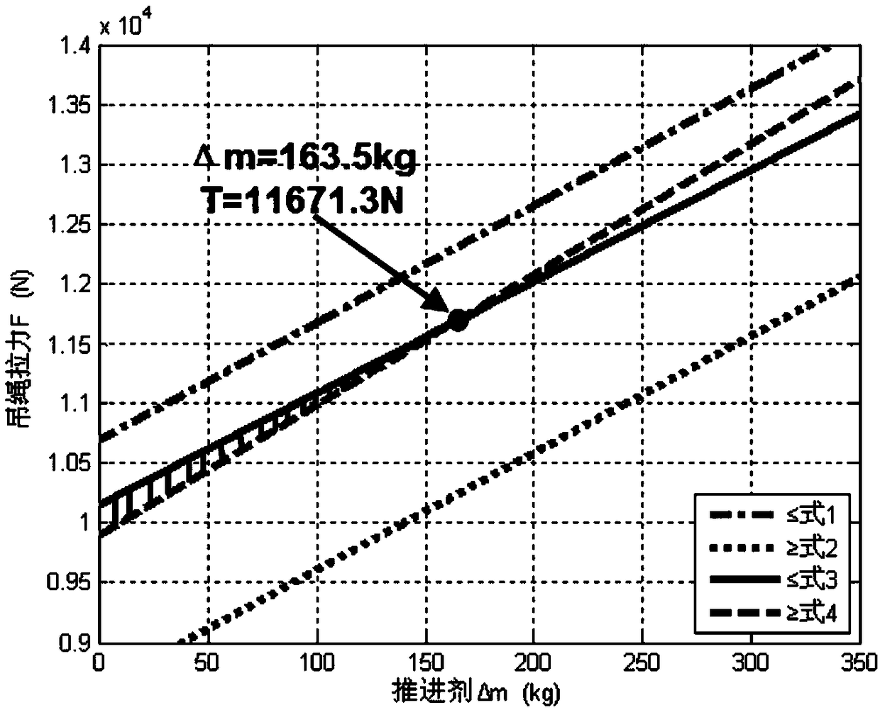
[0048] Solve the inequalities (1)~(4) according to the constraint formula...


PUM


Abstract

The invention provides a method of simulating stress state of a detector in a soft landing test. The method of simulating stress state of a detector in a soft landing test includes the steps: throughthe engine thrust Tx of the detector and the downward and upward simulated acceleration a' up and a' down of the detector under different stress state of the detector in the soft landing test, and bymeans of assistance of the lifting rope tension, depending on adjusting and control of the engine thrust, enabling the stress state of the detector to consistent with the real soft landing process soas to accurately simulate the soft landing process in which the magnitude and the direction of the resultant force born by the detector in the vertical direction continuously changes, thus enabling the method of simulating stress state of a detector in a soft landing test can be applied to ground soft landing verification tests of other planetary surfaces, such as a lunar probe and a Mars probe.

Description

technical field [0001] The invention belongs to the field of deep space exploration, in particular to a method for simulating the stressed state of a detector in a soft landing test. Background technique [0002] With the expansion of the field of deep space exploration, it is an inevitable process for the development of detection technology to carry out landing detection on the surface of the moon, Mars, asteroids and other celestial bodies. Deep space probes need to have the ability of autonomous guidance, navigation and control. The core design element of the landing mission. Due to the importance of the soft landing flight mission, complex control, irreversible process, and high reliability requirements, ground verification tests need to be carried out during the development of the detector. The gravity and atmospheric environment under ground conditions are different from those on the surface of other celestial bodies. It is impossible to fly only relying on the thrust...

Claims


Application Information

Patent Timeline
Patent Type & Authority Applications(China)
IPC IPC(8): G01M99/00
CPCG01M99/005
Inventor 任德鹏李青赵洋许映乔马继楠
Owner BEIJING INST OF SPACECRAFT SYST ENG
Learn More