Rotary type electromagnet

An electromagnet, rotary technology, applied in the direction of electromagnets and electromagnets with armatures, can solve the problems of entering impurities and moisture, wasting manpower and resources, accelerating the speed of corrosion and rusting of moving parts, and achieves increased locking. the effect of the ability

CN108766711APending Publication Date: 2018-11-06苏州耀德科电磁技术有限公司
0 Cites 0 Cited by

Patent Information

Authority / Receiving Office
CN · China
Patent Type
Applications(China)
Current Assignee / Owner
Publication Date
2018-11-06

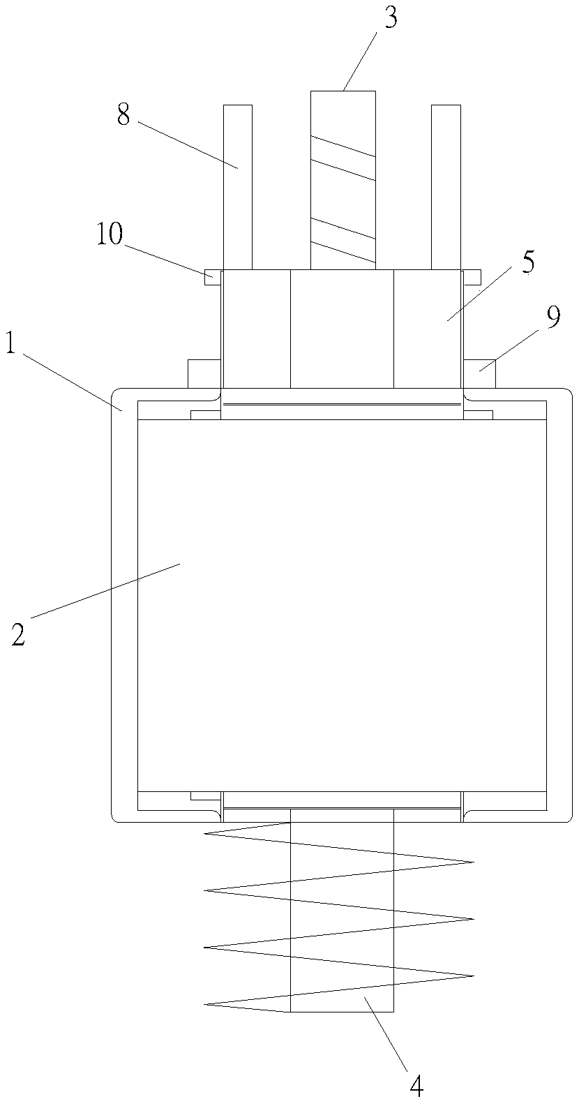
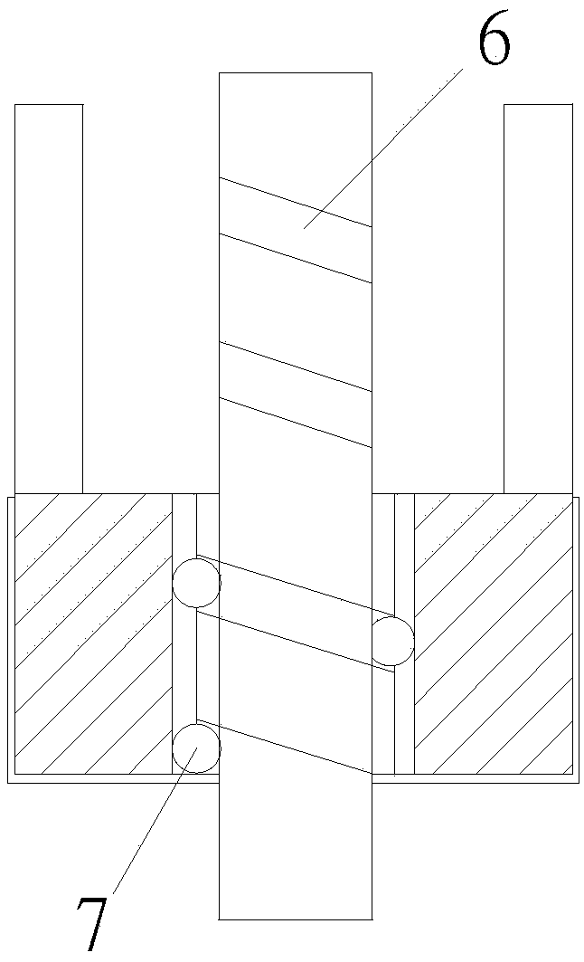
Smart Images

  • Figure 1
    Figure 1
  • Figure 2
    Figure 2
Patent Text Reader

Abstract

The invention discloses a rotary type electromagnet. The rotary type electromagnet comprises an outer frame, a static iron core and a movable iron core, wherein the static iron core is coaxially installed inside the outer frame, and a coil is wound on the static iron core; the movable iron core is coaxially matched in the static iron core; a center pole passing through the outer frame is arrangedon the central spindle of the movable iron core; one end of the center pole is a telescopic working end, and the other end of the center pole is a limiting end for thrust limiting; a rotary disc is arranged on the working end in a sleeving manner; the rotary disc is movably connected with the outer fame; a spiral inner ball groove is formed in the axle hole of the rotary disc, and a correspondingouter ball groove is formed in the working end; stainless steel balls are matched between the inner ball groove and the outer ball groove; a tapered end parallel to the working end is arranged on therotary disc; the movable iron core telescopes to drive the rotary disc to rotate, and the tapered end rotates around the working end. The rotary type electromagnet is additionally provided with a locking structure capable of generating rotation along with the telescoping of a push rod, the rotary type electromagnet is used for coordination in the specific locking structure, the capacity of increasing locking can be achieved, and the push rod also can be avoided from being impacted by external force.
Need to check novelty before this filing date? Find Prior Art

Description

technical field

[0001] The invention relates to the field of electromagnet structure, in particular to a rotary electromagnet. Background technique

[0002] An electromagnet is a device that generates electromagnetism when energized. After inserting an iron core inside the coil, the iron core is magnetized by the magnetic field of the coil. The electromagnets on the market usually include a bracket, a coil and a telescopic rod. The bracket is fixedly connected to the coil. There are through holes on the bracket. The telescopic rod includes a push rod and a top sleeve. The setting of the through hole makes it easy for the electromagnet to enter impurities and water from the through hole during use. The impurities include oil stains, dust, etc. The water will accelerate the corrosion and rust of the moving parts. The impurities and rust will affect the smooth movement of the moving parts. Ultimately, the electromagnet cannot work normally, so it needs to be dismantled and rep...

Examples

Embodiment Construction

[0010] The preferred embodiments of the present invention will be described in detail below in conjunction with the accompanying drawings, so that the advantages and features of the present invention can be more easily understood by those skilled in the art, so as to define the protection scope of the present invention more clearly.

[0011] Please refer to the attached figure 1 and 2 , the embodiment of the present invention includes:

[0012] A rotary electromagnet, comprising an outer frame 1, a static iron core 2 and a moving iron core, the static iron core 2 is coaxially installed in the outer frame 1, and coils are wound on the static iron core 2; the moving iron core is coaxially matched with the static iron core Inside the iron core 2; the shaft core of the moving iron core is provided with a central rod that runs through the outer frame; one end of the central rod is a telescopic working end 3, and the other end is a limit end 4 that is thrust-limited; A rotating di...