Two-dimensional beam deflection Fabry-Perot resonant cavity antenna

A resonant cavity antenna, beam technology, applied in the field of communication

Inactive Publication Date: 2018-11-06
XIDIAN UNIV
View PDF5 Cites 28 Cited by
  • Summary
  • Abstract
  • Description
  • Claims
  • Application Information

AI Technical Summary

Problems solved by technology

Large-angle two-dimensional beam deflection characteristics are realized in the working frequency band

Method used


Image

  • Two-dimensional beam deflection Fabry-Perot resonant cavity antenna
  • Two-dimensional beam deflection Fabry-Perot resonant cavity antenna
  • Two-dimensional beam deflection Fabry-Perot resonant cavity antenna

Examples


Embodiment Construction

[0019] The present invention will be described in further detail below in conjunction with the accompanying drawings.

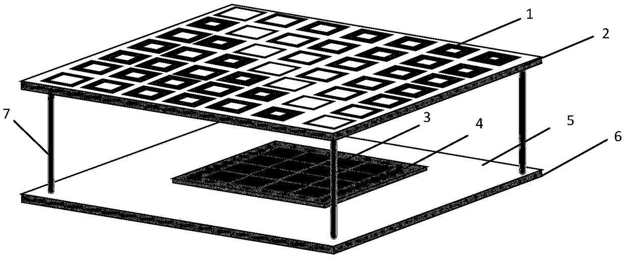
[0020] Refer to attached figure 1 , the structure of the present invention is described in further detail.

[0021] refer to figure 1 , including a reflective coating 1 , a dielectric substrate 2 , a metamaterial structure 3 , a dielectric substrate 4 , a reflective structure 5 , a dielectric substrate 6 and a support column 7 .

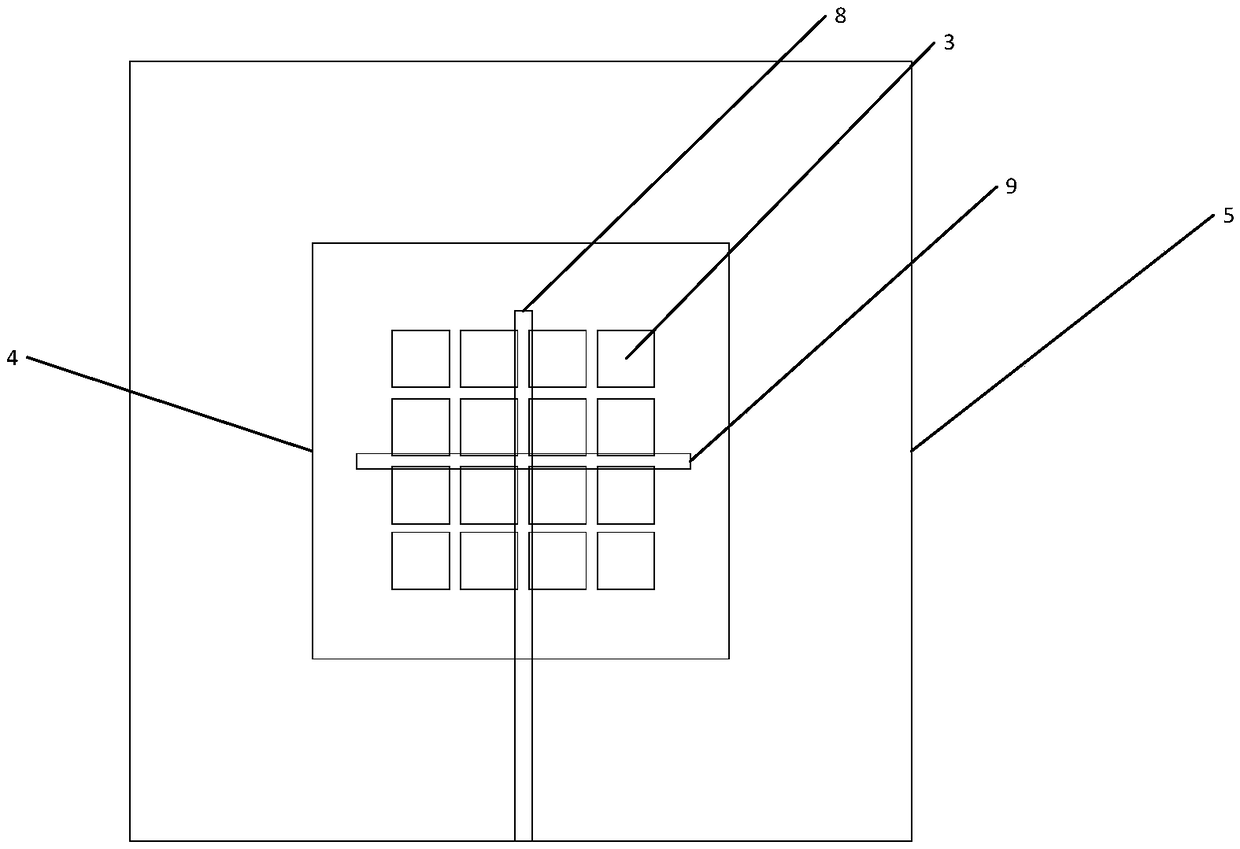
[0022] The metamaterial structure 3 is composed of 16 rectangular metal patches of the same size in four groups of four patches. The four rectangular metal patches in each group are arranged symmetrically along the center of the x-axis of the dielectric substrate 4. The groups of rectangular metal patches are symmetrically arranged along the center of the y-axis of the dielectric substrate 4 .

[0023] The metamaterial structure 3 is located on the upper surface of the dielectric substrate 4 with a relative permittivity between 2...


PUM


Abstract

The invention discloses a two-dimensional beam deflection Fabry-Perot resonant cavity antenna. The two-dimensional beam deflection Fabry-Perot resonant cavity antenna comprises a reflection coverage layer, a dielectric substrate, a metasurface structure, a dielectric substrate, a reflection structure, a dielectric substrate, a feeding structure and a support post, wherein the reflection coverage layer comprises reflection units gradually changing in a two-dimensional direction, the metasurface structure comprises a plurality of rectangular patches, the reflection structure is a metal floor etched with a gap, the feeding structure is a microstrip feeding structure, and the support post comprises four nylon posts. The reflection units in 300-degree phase gradient changing are employed, large-angle and two-dimensional beam deflection is achieved within a working frequency band by two-dimensional arrangement of the unit structures, and thus, the problem that the main beam direction of theantenna cannot be adjusted to cause beam directivity during limitation of the antenna installation space is prevented.

Description

technical field [0001] The invention belongs to the field of communication technology, and further relates to a two-dimensional beam deflection Fabry-Perot F-P, Fabry-Perot resonant cavity antenna in the field of electromagnetic field and microwave technology. The present invention realizes a Fabry-Perot (F-P) resonant cavity antenna with large-angle two-dimensional beam deflection, which can be used for beam directivity caused by the main beam direction of the antenna being unable to be adjusted when the antenna installation space is limited . Background technique [0002] With the development of wireless communication technology, the performance requirements of the antenna are not only limited to miniaturization, high gain, and wide frequency band, but also the beam directivity of the antenna under conformal conditions. Traditional high-gain beam-steering antennas usually have large volumes and complex feed networks, while Fabry-Perot (F-P) resonant cavity antenna structu...

Claims


Application Information

Patent Timeline
Patent Type & Authority Applications(China)
IPC IPC(8): H01Q19/10H01Q15/14H01Q1/38H01Q1/48H01Q1/50
CPCH01Q1/38H01Q1/48H01Q1/50H01Q15/148H01Q19/10
Inventor 刘英杨雪瑞杨旭龚书喜
Owner XIDIAN UNIV
Why Eureka
Try Eureka